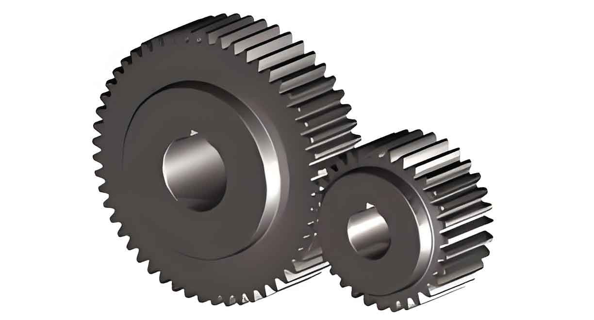
This study investigates the effects of pressure relief hole diameter in steel billets on mold elastic deformation during cold precision forging of spur gears. Using radial shunting principles, billets with varying pressure relief hole diameters (d₀) were designed and analyzed through finite element modeling to optimize gear dimensional accuracy. The following sections present methodologies, computational models, and experimental validations.
1. Numerical Modeling Framework

The spur gear model (module: 3 mm, teeth: 24, pressure angle: 20°) was simulated using DEFORM-3D. Billets with d₀ = Φ0, Φ5, Φ10, Φ15, and Φ20 mm were designed under volume constancy:
$$ V_0 = V_f \Rightarrow \frac{\pi}{4}D_0^2h_0 = \frac{\pi}{4}(D_f^2 – d_0^2)h_f $$
where \( D_0 \), \( h_0 \), \( D_f \), and \( h_f \) represent initial/final diameters and heights. Material properties are listed below:
| Material | Elastic Modulus (GPa) | Poisson’s Ratio | Yield Strength (MPa) |
|---|---|---|---|
| 20CrMnTiH Steel | 207 | 0.25 | 835 |
| H13 Steel | 210 | 0.30 | 1750 |
2. Load-Stroke Behavior and Stress Analysis
Simulated load-stroke curves revealed three stages: initial rapid loading, steady-state flow, and final densification. Maximum forging loads (Fmax) varied with d₀:
| d₀ (mm) | Φ0 | Φ5 | Φ10 | Φ15 | Φ20 |
|---|---|---|---|---|---|
| Fmax (kN) | 8589 | 8689 | 8551 | 8484 | 8217 |
Mold stress distributions showed peak von Mises stress at tooth tips due to concentrated deformation. Stress magnitude followed:
$$ \sigma_{eq} \propto \frac{F_{\text{max}}}{A_{\text{contact}}} $$
where \( A_{\text{contact}} \) is the effective contact area between billet and mold.
3. Elastic Deformation Characteristics
Elastic displacements (δ) at upper, middle, and lower profile planes of the spur gear mold were quantified. Key observations include:
- Maximum δ occurred at tooth tips (0.591 mm for d₀=Φ0 mm)
- Deformation decreased with increasing d₀ beyond Φ10 mm
- Upper profile exhibited 28.6% higher δ than lower regions
The displacement gradient along the tooth profile followed:
$$ \delta(x) = \delta_{\text{root}} + kx^2 $$
where \( x \) is the distance from tooth root, and \( k \) is a load-dependent coefficient.
4. Tooth Profile Compensation
Inverse compensation reduced elastic deviations by 28.6%. The corrected tooth profile equation was derived as:
$$ y_{\text{comp}}(x) = y_{\text{nom}}(x) – \delta(x) $$
Post-compensation forging experiments confirmed dimensional improvements:
| d₀ (mm) | Φ0 | Φ10 | Φ20 |
|---|---|---|---|
| Deviation (mm) | 0.376 | 0.312 | 0.220 |
5. Experimental Validation
Cold forging trials using a 10,000 kN hydraulic press validated simulation trends. Spur gears with d₀=Φ20 mm achieved IT9-IT10 accuracy, demonstrating the efficacy of pressure relief hole optimization.
6. Conclusions
- Optimal d₀=Φ20 mm minimized mold elastic deformation (δmax=0.486 mm)
- Tooth tip regions showed 2.1× higher δ than roots
- Inverse profile compensation reduced post-forging deviations by 28.6%
This work provides actionable insights for designing high-precision spur gear cold forging processes through systematic pressure relief hole optimization and mold elasticity compensation.
