
The influence of the change of the relative position of the outer split surface on the tooth shape quality of the spiral bevel gear is studied based on the determination of the position of the inner split surface. Combined with the conclusions obtained in the previous summary, this section sets the position of the inner shunting surface farthest from the tooth shape of the female die by adjusting the relative position of the die core of the male and female die. When the distance between the inner shunting gap is 5mm and the distance between the outer shunting gap is 4mm, the shape of the preform remains unchanged. Under the condition of ensuring a certain volume, the numerical simulation is carried out by adjusting the relative height of the upper and lower dies to study the different positions of the outer shunting surface, Its spiral bevel gear tooth form quality.
Through the finite element numerical simulation, it can be seen that the different positions of the outer shunting surface also have an impact on the forming quality of the spiral bevel gear tooth profile. As shown in Figure 1, the positions of the outer shunting surface can be divided into three areas: A, B and C. different shunting areas affect the forming quality of the spiral bevel gear tooth profile and the forming force.
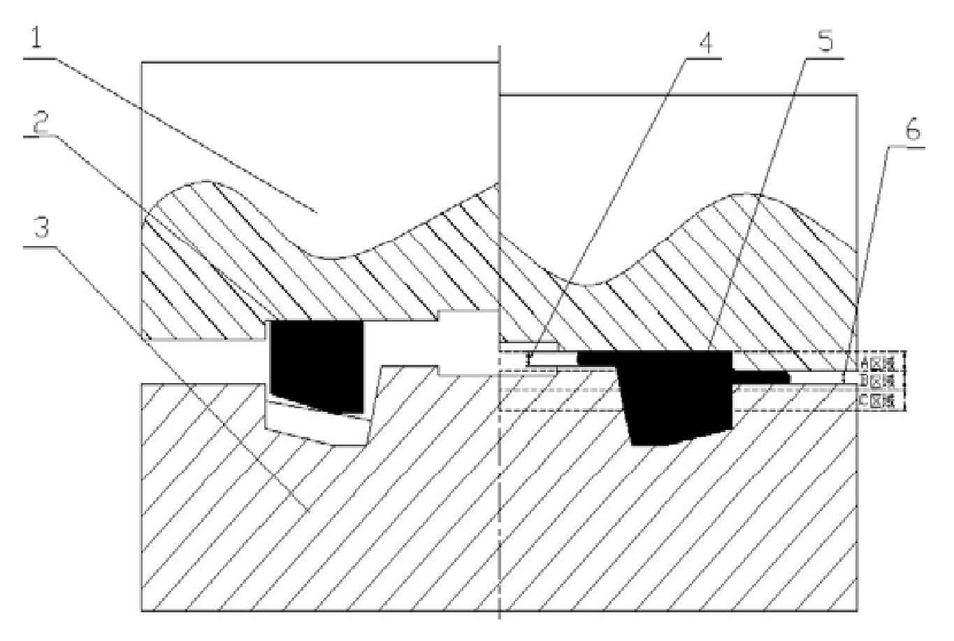
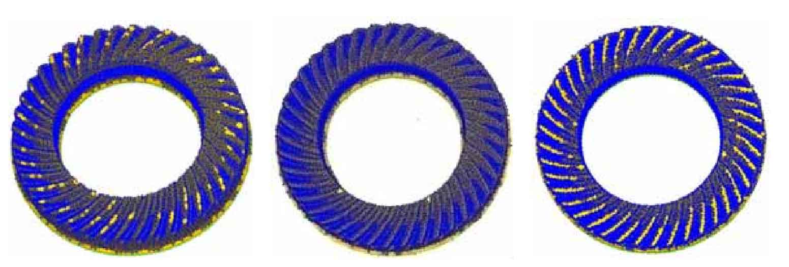
When the outer split surface is located in area a (as shown in Figure 1), the formed tooth profile of spiral bevel gear is shown in Figure 2 (a). At this time, the tooth profile filling of spiral bevel gear is not full enough and the forming quality is not ideal. When the shunting surface is located in area B, the formed tooth shape is shown in Figure 2 (b). The tooth shape of spiral bevel gear is filled very fully and the forming quality is good. When the outer shunting surface is located in area C, the formed tooth profile is shown in Figure 2 (c), the tooth profile filling of spiral bevel gear is not full, and the forming quality is poor.
According to the above analysis results, by changing the relative position of the upper and lower molds, move the position of the outer shunting surface from top to bottom in the unit of 2mm. Under the condition of ensuring that all other parameters are fixed, carry out the finite element numerical simulation, analyze the simulation results, and draw the rule: the upper end of the outer shunting surface is 2mm lower than the lower end of the inner shunting surface, which is the best position of the outer shunting surface. At this time, the tooth shape of the spiral bevel gear is fully filled, And the forming force is less than that of the following parts (in area B, the forming force when the position of the outer shunting surface is close to the tooth shape of the female die).
The reason for the above is that when the outer shunting surface is located in area a, the flow speed of the metal material at the inner shunting gap is greater than that at the outer shunting gap, resulting in the premature outflow of the metal material from the inner shunting gap, resulting in insufficient blank volume and insufficient filling of the tooth shape of the spiral bevel gear. When the outer shunting surface is located in area C, the flow speed of metal materials at the outer shunting gap is greater than that at the inner shunting gap. Excessive metal materials flow out of the outer shunting gap, resulting in waste of materials. The tooth shape of spiral bevel gear is also not fully filled. When the outer split surface is located in area B, there is little difference in the flow velocity between the inward split gap and the outer split gap, resulting in the simultaneous outflow of metal materials from the inner and outer split gap. At this time, the tooth shape of spiral bevel gear is fully filled, and it is determined as the best position of the outer split surface.