Abstract
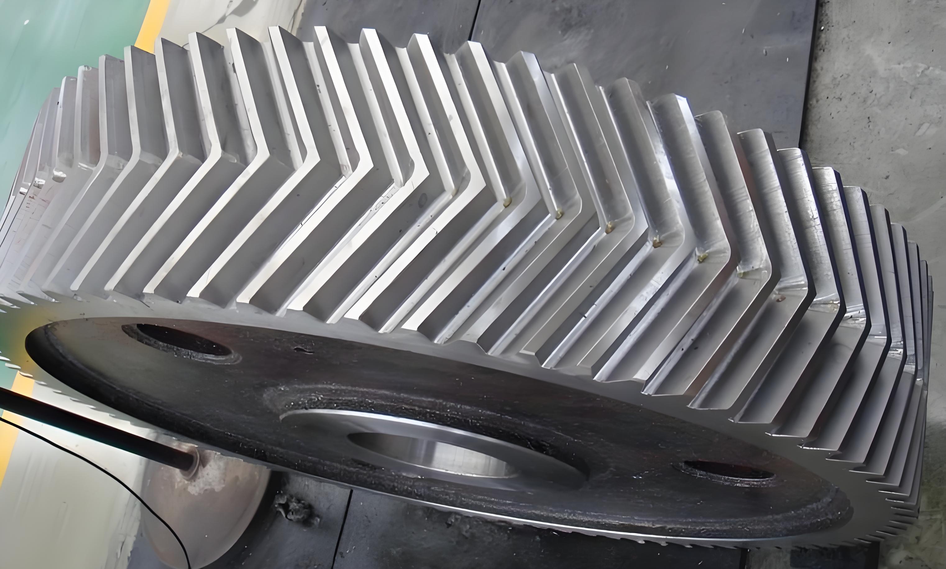
To reveal the influence of cracks on the vibration characteristics of a two-stage herringbone gear system, a 48-degree-of-freedom bending-torsion-axis-pendulum coupling dynamics model is established, considering factors such as cracks, time-varying mesh stiffness, undercut, and errors. The potential energy method is employed to calculate the time-varying mesh stiffness of each gear pair in the system. The Runge-Kutta numerical integration method is used to obtain time-domain, frequency-domain, phase diagram, and Poincare map representations of vibration characteristics. Experimental comparisons are made between normal and cracked gears. Results show that cracks reduce the time-varying mesh stiffness and intensify system vibrations, with periodic impact phenomena and sidebands near mesh harmonics. Theoretical and experimental findings align well, providing theoretical support for system dynamic design.

1. Introduction
Vibration and noise are ubiquitous in gear transmission systems. Many scholars have established dynamic models using methods such as the lumped mass parameter method and Lagrange method, analyzing the influence of tooth profile modification, tooth surface friction, etc., on time-varying mesh stiffness and vibration response characteristics. However, research on herringbone gears with cracks, especially considering additional degrees of freedom for accurate modeling and calculations, is insufficient.
2. Dynamic Model Establishment
Table 1: System Parameters
| Parameters | First-stage Driver | First-stage Driven | Second-stage Driver | Second-stage Driven |
|---|---|---|---|---|
| Module (mm) | 4 | 4 | 4 | 4 |
| Number of Teeth | 25 | 60 | 25 | 75 |
| Face Width (mm) | 20 | 20 | 20 | 20 |
| Helical Angle β (°) | 10 | 10 | 10 | 10 |
| Mass (kg) | – | – | – | – |
(Note: Mass values are not provided in the snippet but are included for completeness of the table format.)
A 48-degree-of-freedom bending-torsion-axis-pendulum dynamics model for a two-stage herringbone gear transmission system is established using the lumped mass parameter method, considering cracks, time-varying mesh stiffness, undercut, and errors.
3. Calculation of Time-Varying Mesh Stiffness for Cracked Herringbone Gears
Assuming the gear teeth are cantilever beams on the tooth root circle, the bending stiffness, compressive stiffness, and shear stiffness are calculated. When cracks occur, the effective moment of inertia and cross-sectional area change, affecting the bending and shear stiffness.
Formulas for Stiffness Calculation
- Bending stiffness kbi, compressive stiffness kai, and shear stiffness ksi expressions (details omitted for brevity).
4. Vibration Response Analysis
Using the Runge-Kutta method, the vibration response of the system is solved. The time-domain, frequency-domain, phase, and Poincare diagrams are analyzed.
- Time-domain Diagrams: Show increasing vibration amplitude with crack length.
- Frequency-domain Diagrams: Demonstrate the emergence and increase of sidebands near harmonics.
- Phase Diagrams: Illustrate wider and more disordered vibration trajectories with cracks.
- Poincare Diagrams: Display progressively dispersed discrete points with increasing cracks.
5. Experimental Verification
Experimental comparisons are made between normal and cracked gears, confirming the model’s accuracy and revealing the mechanism of crack influence on the herringbone gear system.
Conclusion
Bending-torsion-axis-pendulum dynamics model for a two-stage herringbone gear system with cracks, analyzes the influence of cracks on time-varying mesh stiffness and vibration characteristics, and verifies the model through experiments. The findings provide theoretical support for the optimization design and engineering practice of herringbone gear systems.
