
The pursuit of enhanced performance, efficiency, and compactness in power transmission systems has consistently driven gear technology forward. Among the most fundamental components in these systems is the spur gear. Its simplicity, ease of manufacture, and reliability make it ubiquitous. However, conventional symmetric spur gear profiles, defined by a single pressure angle on both flanks, present inherent limitations regarding load capacity, wear resistance, and noise, especially in high-speed or heavily loaded applications such as aerospace, marine propulsion, and advanced machinery. This has led to the exploration and development of asymmetric involute spur gear designs, which offer a significant performance leap. This article details, from a first-person research and development perspective, the comprehensive design methodology, mathematical modeling, and the development of a specialized computational system for asymmetric involute spur gears.
The core innovation of an asymmetric spur gear lies in its tooth profile. Unlike a standard gear, its two flanks are generated from two different base circles, resulting in two distinct pressure angles: a larger pressure angle on the drive (or “working”) flank and a smaller pressure angle on the coast flank. This deliberate asymmetry allows engineers to tailor the gear’s performance characteristics. The primary benefits are substantial: increasing the pressure angle on the working flank raises the tooth’s effective bending strength and, crucially, increases the radius of curvature at the point of contact. A larger contact curvature radius directly reduces Hertzian contact stresses, which are a primary cause of surface pitting and fatigue. Furthermore, it can improve lubricant film thickness between meshing teeth, reduce friction and wear, and contribute to lower operational vibration and noise. Designing such a gear, however, introduces complexity that surpasses standard symmetric spur gear calculations, particularly in accurately determining the root bending stress, necessitating a sophisticated computational approach.
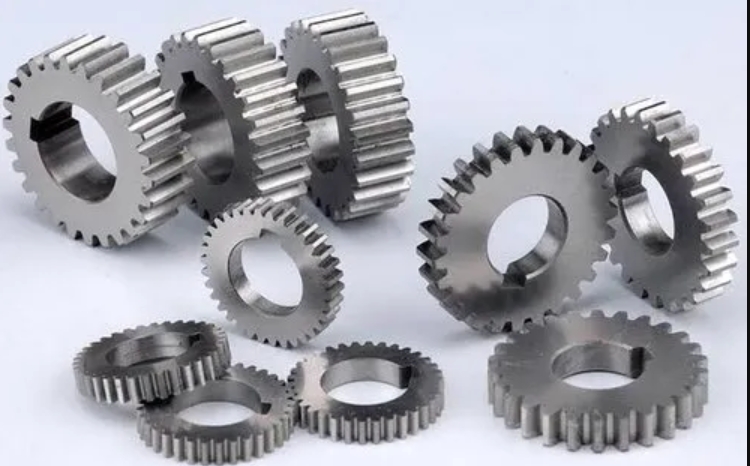
The visual representation above illustrates the classic form of a spur gear. In our asymmetric design paradigm, the tooth profile would deviate from this symmetric ideal, with one flank being distinctly steeper than the other. The development of a robust design system for such gears requires establishing a precise mathematical foundation. For contact strength (pitting resistance), the standard formulas from AGMA or ISO standards for symmetric gears can be adapted, as the fundamental Hertzian theory remains valid, provided the correct geometry for the working flank is used. The critical challenge lies in the bending strength calculation. The tooth form factor (Y) or stress correction factor for a symmetric spur gear is not applicable. A new analytical model must be derived to calculate the maximum tensile stress at the root fillet of the asymmetric tooth, specifically under load applied to the tip of the working flank.
The bending stress at the root of an asymmetric involute spur gear tooth, $\sigma_F$, is governed by the Lewis equation principle but requires a specialized form factor. The fundamental formula is:
$$ \sigma_F = \frac{F_t}{b m_n} Y_{FS} Y_\epsilon Y_\beta K_A K_V K_{F\alpha} K_{F\beta} $$
Where $F_t$ is the nominal tangential load, $b$ is the face width, $m_n$ is the normal module, $Y_\epsilon$ is the contact ratio factor, $Y_\beta$ is the helix angle factor (1 for spur gears), and $K_A$, $K_V$, $K_{F\alpha}$, $K_{F\beta}$ are the application, dynamic, transverse load, and face load factors, respectively. The pivotal term is $Y_{FS}$, the compound tooth form factor for the asymmetric spur gear. This factor is calculated as:
$$ Y_{FS} = \frac{1}{\frac{s_{Fn}}{h_{Fe}} \cdot \frac{\cos\alpha_{Fan}}{\cos\alpha_{n,work}}}} $$
Here, $\alpha_{n,work}$ is the normal pressure angle on the working flank. The parameters $s_{Fn}$ (tooth thickness at the critical root section) and $h_{Fe}$ (bending moment arm) are determined through a detailed geometric analysis of the asymmetric profile. Their calculation involves the following sequence:
1. Load Angle $\alpha_{Fan}$: This is the angle between the line of action and a line perpendicular to the tooth centerline at the load application point (tip).
$$ \alpha_{Fan} = \alpha_{n,a,work} – \Delta\alpha $$ where $\alpha_{n,a,work}$ is the working flank pressure angle at the tip circle and $\Delta\alpha$ is the tooth tip thinning angle for the working flank.
2. Bending Moment Arm $h_{Fe}$:
$$ h_{Fe} = 0.5 \left( \frac{d_{a,work}}{ \cos\alpha_{Fan}} – \frac{d_{b,work}}{\cos\alpha_{n,work}} \right) – \rho_F $$ where $d_{a,work}$ is the tip diameter on the working side, $d_{b,work}$ is the base diameter of the working flank, and $\rho_F$ is the root fillet radius parameter.
3. Critical Root Section Thickness $s_{Fn}$: This is found by calculating the chordal distance at the 30° tangent point of the root fillet relative to the tooth centerline.
$$ s_{Fn} = 2 \left( \rho_F + \frac{m_n}{2} – x_n m_n \right) \sin\left( \frac{\pi}{2Z_v} – \text{inv}\alpha_{n,work} – \frac{\theta_F}{3} \right) $$
Here, $x_n$ is the normal profile shift coefficient, $Z_v$ is the virtual number of teeth, $\text{inv}$ is the involute function, and $\theta_F$ is an angular parameter related to the fillet geometry.
4. Root Fillet Parameter $\rho_F$:
$$ \rho_F = \frac{\rho_{FC}}{ \cos\alpha_{nF} } $$ where $\rho_{FC}$ is the radius of curvature at the critical root section and $\alpha_{nF}$ is the pressure angle at that point on the working flank. The calculation of $\rho_{FC}$ itself is iterative, involving the intersection of the trochoid (generated by the cutter tip) and the line defining the critical section.
This intricate set of interdependent equations highlights why manual calculation for an asymmetric spur gear is impractical and error-prone. To address this, we developed a dedicated computational system. The system’s architecture was guided by modular design principles, ensuring clarity, maintainability, and ease of debugging. The core modules are:
| System Module | Primary Function |
|---|---|
| Data Input Module | Accepts user parameters: power, speed, material properties, desired asymmetry ratio ($\alpha_{work}/\alpha_{coast}$), space constraints, etc. |
| Design & Calculation Engine | • Geometry Synthesis • Contact Strength Analysis • Asymmetric Bending Stress Analysis • Iterative Optimization & Standardization |
| Output & Reporting Module | • Detailed Parameter Reports • Safety Factor Validation • Data Export for CAD/CAE |
A significant challenge in automating gear design is the handling of empirical charts and tables (e.g., for application factor $K_A$, dynamic factor $K_V$, zone factors $Z_H$, $Z_E$). Our system programmatically integrates this data. For graphical relationships, we employed the least-squares method to derive accurate polynomial approximations. For tabular data, we implemented piecewise linear interpolation algorithms. This allows the system to automatically query all necessary design coefficients, run the calculations, analyze results against allowable stresses, and iteratively adjust parameters (like module or profile shift) until an optimal and safe design for the asymmetric spur gear is achieved. The system also performs rounding and standardization of values (e.g., to preferred module series).
The user interface was built to be intuitive, guiding the engineer through the process. The user can specify whether they are designing a new asymmetric spur gear pair or performing a safety check on an existing geometry. Key input parameters are summarized below:
| Input Category | Example Parameters |
|---|---|
| Power Transmission | Input Power (kW), Input Speed (rpm), Service Factor |
| Geometric Constraints | Center Distance, Face Width, Minimum Teeth |
| Material & Heat Treatment | Grade, Ultimate Tensile Strength, Hardness |
| Asymmetry Definition | Working Flank Pressure Angle ($\alpha_{work}$), Coast Flank Pressure Angle ($\alpha_{coast}$) |
| Manufacturing | Cutter Tip Radius, Manufacturing Quality Grade |
Upon execution, the system performs thousands of calculations in seconds. The output provides a complete geometric and strength summary for the asymmetric spur gear, as illustrated in the following sample output structure:
| Output Parameter | Pinion | Gear |
|---|---|---|
| Normal Module, $m_n$ (mm) | 3.0 | 3.0 |
| Number of Teeth, $Z$ | 24 | 72 |
| Working Pressure Angle, $\alpha_{work}$ | 25° | 25° |
| Coast Pressure Angle, $\alpha_{coast}$ | 20° | 20° |
| Profile Shift Coefficient, $x_n$ | +0.4 | +0.2 |
| Contact Ratio, $\epsilon_\alpha$ | 1.68 | |
| Calculated Bending Stress, $\sigma_F$ (MPa) | 142 | 128 |
| Allowable Bending Stress, $\sigma_{FP}$ (MPa) | 280 | 260 |
| Bending Safety Factor, $S_F$ | 1.97 | 2.03 |
| Calculated Contact Stress, $\sigma_H$ (MPa) | 850 | |
| Allowable Contact Stress, $\sigma_{HP}$ (MPa) | 1100 | |
| Contact Safety Factor, $S_H$ | 1.29 | |
It is crucial to note that the formulas for contact stress $\sigma_H$, while similar in form to standard formulas, utilize the geometry of the working flank:
$$ \sigma_H = Z_H Z_E Z_\epsilon Z_\beta \sqrt{ \frac{F_t}{b d_1} \frac{u+1}{u} K_A K_V K_{H\alpha} K_{H\beta} } $$
Where $Z_H$ is the zone factor (a function of $\alpha_{work}$ and profile shift), $Z_E$ is the elasticity factor, $Z_\epsilon$ is the contact ratio factor, and $d_1$ is the pinion’s pitch diameter. The system automatically calculates the correct $Z_H$ for the asymmetric pressure angle condition.
The versatility of this computational system is a key feature. While its primary purpose is the design of high-performance asymmetric spur gears, it is fully capable of handling conventional symmetric spur gear designs by simply setting $\alpha_{work} = \alpha_{coast}$. This makes it a universal tool for gear design engineers and an excellent educational resource for students, allowing for direct comparison between symmetric and asymmetric solutions for the same load case. The system’s output, particularly the precise geometric coordinates derived from the asymmetric involute equations, can be directly fed into parametric CAD software for model generation and into FEA systems for detailed verification, creating a seamless digital thread from design to analysis.
In conclusion, the transition from symmetric to asymmetric involute profiles represents a meaningful advancement in spur gear technology, unlocking higher power density and longevity. The complexity of their design, however, acts as a barrier to widespread adoption. The computational system developed and described here effectively dismantles this barrier. By establishing a rigorous mathematical model for asymmetric tooth root stress, implementing a modular and automated calculation engine, and providing a user-friendly interface, it transforms a theoretically superior concept into a practically designable component. This system not only significantly reduces design time and increases accuracy but also serves as a foundational platform for further research and optimization in specialized spur gear applications, paving the way for their increased use in demanding engineering fields.