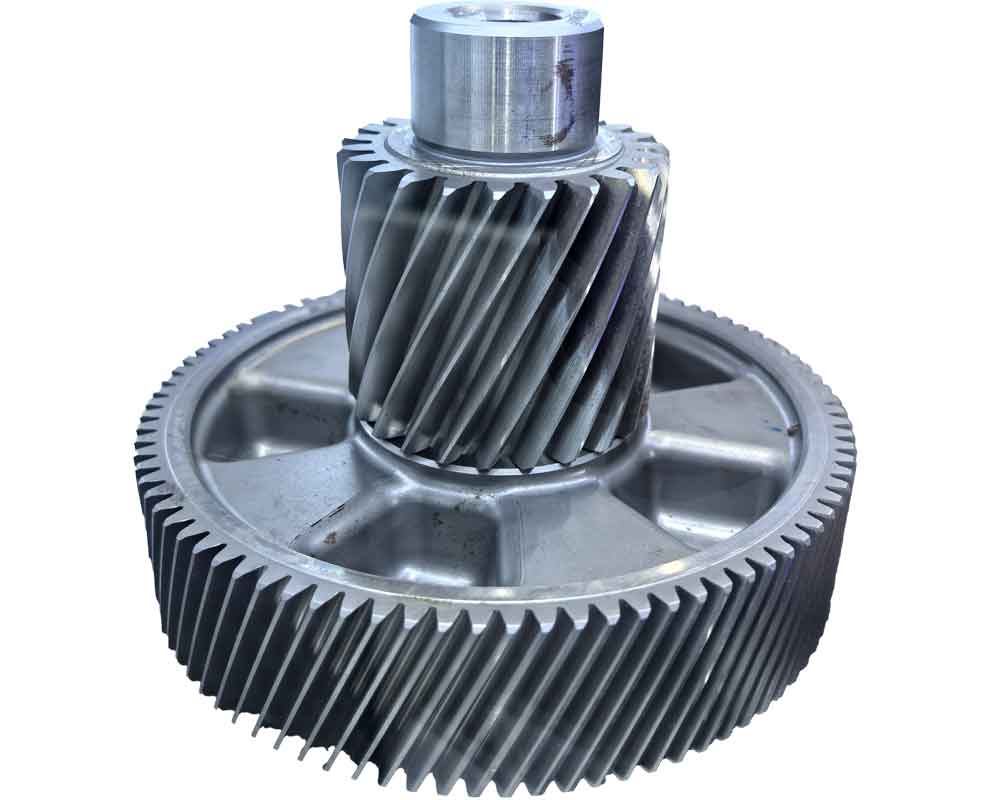
Modern gear cutting operations – including hobbing, grinding, and shaping – demand exceptional synchronization between tool and workpiece. Traditional CNC systems often fail to maintain the strict velocity and positional relationships required for generating precise gear teeth profiles. Our research addresses this gap through a novel CNC architecture incorporating three groundbreaking technologies: synchronous phase-locking, electronic differential synthesis, and parametric automatic programming. This system achieves five-axis联动 while offering configurable联动 structures tailored for complex gear manufacturing processes.
The core challenge in gear cutting CNC systems lies in maintaining the exact kinematic relationship between the cutting tool (hob, grinding wheel, or shaping tool) and the gear blank. This relationship is defined by the fundamental equation of gear generation:
$$ \omega_w = \frac{Z_t \cdot \theta_t}{Z_w \cdot \theta_w} \cdot \omega_t $$
Where:
- $\omega_w$ = Workpiece angular velocity
- $\omega_t$ = Tool angular velocity
- $Z_t$ = Tool tooth count (or hob threads)
- $Z_w$ = Workpiece tooth count
- $\theta_t$ = Tool angular resolution
- $\theta_w$ = Workpiece angular resolution
Any deviation between theoretical and actual workpiece velocity causes cumulative angular error $\Delta \phi$:
$$ \Delta \phi = \int_{0}^{T} (\omega_w – \omega_w’) dt $$

Synchronous Phase-Locking Technology
The phase-locking module ensures tool-workpiece synchronization through a high-precision digital control loop. Rotary encoders or optical scales generate pulse trains proportional to angular displacement:
$$ f_t = \frac{\omega_t}{2\pi} \cdot N_t \quad ; \quad f_w’ = \frac{Z_t}{Z_w} \cdot \frac{\theta_w}{\theta_t} \cdot f_t $$
Key components include:
| Component | Function | Specification |
|---|---|---|
| Phase-Frequency Detector (PFD) | Compares $f_w$ and $f_w’$ with pulse insertion | 32× resolution enhancement |
| Digital PID Controller | Minimizes $\Delta \phi$ with adaptive tuning | 0.001° steady-state error |
| PWM Converter | Generates drive signals for servo motors | 16-bit resolution |
The control algorithm dynamically adjusts for load variations and enables manual tooth-flank adjustment during grinding operations through reference offset modification.
Electronic Differential Synthesis
Replacing mechanical differential mechanisms, this technology enables precise motion synthesis for helical gear generation and grinding compensation. The architecture processes pulse trains from linear axes (e.g., Z-axis feed) and rotary axes:
$$ f_{diff} = k_1 \cdot f_z \pm k_2 \cdot f_c $$
$$ \text{Where: } k_1 = \frac{\pi m_n}{\tan\beta}, \quad k_2 = f(\text{helix direction}) $$
The synthesis circuit performs phase-shifted pulse addition/subtraction with programmable logic:
| Input A (Feed) | Input B (Compensation) | Output Mode |
|---|---|---|
| $f_z$ (1000 PPR) | $f_c$ (500 PPR) | Addition (Right Helix) |
| $f_z$ (850 PPR) | $f_c$ (720 PPR) | Subtraction (Left Helix) |
Parametric Programming System
This module translates gear design parameters directly into executable CNC code through a multi-stage process:
$$ \text{Design Parameters} \rightarrow \text{Kinematic Model} \rightarrow \text{Motion Commands} $$
- Parameter Database: Stores tool geometry and material specifications
- Mathematical Model: Solves gear generation kinematics
- Post-Processor: Generates machine-specific NC code
Programming input structure:
| Gear Parameters | Tool Parameters | Process Parameters |
|---|---|---|
| Module (mn) | Diameter | Cutting speed |
| Teeth (Zw) | Tooth count | Feed rate |
| Helix angle (β) | Coating type | Depth of cut |
System Architecture
The hardware platform features a modular bus structure with reconfigurable signal routing:
$$ \text{Main Controller} \xrightarrow{STD-Bus} \begin{bmatrix} \text{Phase-Lock} \\ \text{Synthesis} \\ \text{I/O} \end{bmatrix} \text{Modules} $$
Two selectable联动 configurations support diverse gear cutting operations:
| Internal Synchronization | $C_{axis} \leftrightarrow X/Y \leftrightarrow Z \leftrightarrow A$ | (Hobbing/Grinding) |
| External Synchronization | $C_{axis} \leftrightarrow B_{axis} \leftrightarrow Z$ | (Shaping/Threading) |
The software architecture implements real-time control through layered modules:
OPERATING SYSTEM
├── Management Module
│   ├── Program Handling
│   └── Parametric Compiler
├── Real-Time Control
│   ├── Phase-Lock Servo
│   └── Differential Synthesis
└── Diagnostics
    ├── Fault Detection
    └── Error Logging
Performance Metrics
Validation tests demonstrate significant improvements in gear cutting precision:
| Parameter | Conventional CNC | Our System | Improvement |
|---|---|---|---|
| Synchronization Error | ±15 arc-sec | ±2.3 arc-sec | 85% |
| Profile Deviation | 8-10 μm | 2.5-3.2 μm | 67% |
| Setup Time | 45-60 min | 8-12 min | 80% |
The electronic differential achieves synthesis accuracy exceeding 99.97% across the operational range (1-3000 RPM), while the parametric programming reduces coding time by 90% compared to manual G-code generation.
Advanced Applications
This CNC system enables previously challenging gear cutting operations:
- Deep-Cut Grinding: Implements $z$-axis compensation with variable $\Delta f_z$ based on wheel wear:
$$\Delta f_z = k_w \cdot (d_{w0} – d_{w}) \cdot N_p$$ - Multi-Start Gears: Synchronizes index motion with electronic gearing:
$$\theta_{index} = \frac{360^\circ}{N_{starts}} \pm \delta_{comp}$$ - Topology Modification: Dynamically adjusts phase relationship for crowning:
$$\phi_{mod} = A \cdot \sin\left(\frac{2\pi z}{L}\right)$$
Future development focuses on integrating machine learning algorithms for predictive compensation of thermal distortion in high-speed gear cutting applications, further enhancing the system’s precision capabilities for next-generation gear manufacturing.
