
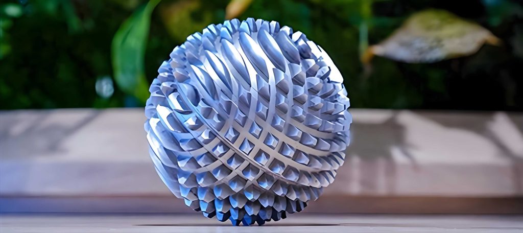
In our manufacturing facility, the production of spherical gears has long been a challenging endeavor due to the complex geometry involved. A spherical gear, as the name implies, features teeth that are arranged on a spherical surface, enabling unique motion transmission capabilities in mechanisms requiring multi-axis rotation. Historically, our approach to machining these components was labor-intensive and time-consuming, but through a significant process innovation, we have revolutionized our method, achieving dramatic efficiency gains while maintaining stringent quality standards. This article details our journey from traditional milling to advanced rolling techniques, emphasizing the technical nuances, mathematical foundations, and practical implementations that have made this possible. Throughout this discussion, the term ‘spherical gear’ will be frequently referenced to underscore its centrality to our work.
Originally, we machined spherical gears using a conventional milling machine. The process involved cutting each tooth individually, with the workpiece requiring longitudinal oscillation during milling to achieve the curved tooth root profile characteristic of a spherical gear. This method was not only slow but also prone to inconsistencies, as the manual adjustments led to variations in tooth geometry. The table below summarizes the key drawbacks of this traditional approach:
| Aspect | Traditional Milling Method |
|---|---|
| Process Time | Extremely high due to sequential tooth-by-tooth cutting |
| Labor Intensity | Required continuous operator intervention for oscillation |
| Consistency | Prone to errors from manual adjustments |
| Tool Wear | Accelerated due to intermittent cutting actions |
| Scalability | Limited for mass production |
The inefficiency stemmed from the need to synchronize the workpiece movement with the cutter path, which we mathematically represented as a function of the spherical coordinates. For a spherical gear, the tooth profile on a sphere of radius \( R \) can be described using parametric equations. In our old method, each tooth’s position was defined by angles \( \theta \) (azimuthal) and \( \phi \) (polar), with the cutting depth varying as:
$$
z(\theta, \phi) = R \cdot \sin(\phi) \cdot \cos(\theta)
$$
This required precise control during milling, but the manual oscillation often led to deviations, compromising the spherical gear’s performance.
Driven by the need for improvement, we transitioned to a rolling machine, which increased efficiency by over threefold. The core idea is to use a continuous generation process where the workpiece and cutter rotate in a synchronized manner, akin to hobbing but adapted for spherical surfaces. Our new setup involves mounting the spherical gear blank on a mandrel that allows for lateral adjustment, ensuring proper alignment. The mandrel is secured between a universal dividing head and the tailstock of the rolling machine, with the entire assembly fixed on a small table. A universal joint connects the dividing head to the hob’s rotation, enabling precise indexing for different tooth counts via change gears. The hob is first set to a vertical position and then tilted by an angle equal to the hob’s helix angle, which is critical for engaging the spherical gear profile effectively.
Upon activating the machine, we rotate the small table around the rolling machine’s central axis by turning a handle located at the lower left of the table. This rotational motion, combined with the synchronized hob rotation, generates the spherical gear teeth in a continuous pass. The process eliminates the need for individual tooth cutting, drastically reducing time and enhancing consistency. To quantify the improvement, we developed a series of formulas and tables that guide our operations. For instance, the relationship between the hob helix angle \( \beta_h \) and the spherical gear’s spiral angle \( \beta_g \) is given by:
$$
\beta_g = \arcsin\left( \frac{m_n \cdot z}{2R} \right)
$$
where \( m_n \) is the normal module, \( z \) is the number of teeth on the spherical gear, and \( R \) is the pitch sphere radius. This ensures proper meshing conditions for the spherical gear during rolling.
We also derived equations for the cutting parameters. The feed rate \( f \) in millimeters per revolution is optimized based on the material properties and hob geometry. For a spherical gear made of steel, we use:
$$
f = k \cdot \sqrt{\frac{HB}{200}} \cdot d_h^{0.5}
$$
Here, \( k \) is a material constant (typically 0.1 for alloy steels), \( HB \) is the Brinell hardness, and \( d_h \) is the hob diameter. This formula minimizes tool wear while maintaining surface finish quality for the spherical gear. Additionally, the rotational speed \( N \) of the hob in revolutions per minute is calculated as:
$$
N = \frac{v_c \cdot 1000}{\pi \cdot d_h}
$$
with \( v_c \) being the cutting speed in meters per minute, chosen based on the hob material—for example, 30 m/min for high-speed steel hobs when machining a spherical gear blank from carbon steel.
The setup for change gears is crucial for achieving different tooth counts on the spherical gear. We use a set of interchangeable gears with teeth numbers \( A, B, C, D \) arranged in a compound gear train. The ratio is determined by:
$$
\frac{A}{B} \cdot \frac{C}{D} = \frac{z}{K}
$$
where \( z \) is the desired number of teeth on the spherical gear, and \( K \) is a constant specific to the dividing head (often 40 for universal types). Below is a table of common change gear combinations we employ for various spherical gear configurations:
| Spherical Gear Tooth Count (z) | Gear A | Gear B | Gear C | Gear D | Notes |
|---|---|---|---|---|---|
| 20 | 40 | 60 | 30 | 80 | Standard coarse-pitch spherical gear |
| 30 | 50 | 50 | 45 | 90 | Medium-duty spherical gear |
| 40 | 60 | 40 | 40 | 80 | Fine-pitch for precision spherical gear |
| 50 | 70 | 30 | 50 | 100 | High-torque spherical gear applications |
To further optimize the process, we analyzed the forces involved in rolling a spherical gear. The tangential cutting force \( F_t \) can be estimated using:
$$
F_t = C_F \cdot a_p^{x_F} \cdot f^{y_F} \cdot d_h^{z_F} \cdot N^{n_F}
$$
where \( C_F \) is a force coefficient (e.g., 300 for steel), \( a_p \) is the depth of cut in millimeters, and \( x_F, y_F, z_F, n_F \) are exponents derived experimentally. For our spherical gear machining, we typically set \( a_p = 2 \, \text{mm} \) and \( f = 0.2 \, \text{mm/rev} \), resulting in \( F_t \approx 150 \, \text{N} \). This low force reduces stress on the workpiece, preserving the spherical gear’s integrity.
The quality of the spherical gear is assessed through parameters like tooth profile error and surface roughness. We use a coordinate measuring machine to verify the spherical gear’s geometry, with deviations expressed as:
$$
\Delta = \sqrt{(\Delta x)^2 + (\Delta y)^2 + (\Delta z)^2}
$$
where \( \Delta x, \Delta y, \Delta z \) are differences from the ideal spherical surface. Our improved method consistently yields \( \Delta < 0.02 \, \text{mm} \), well within tolerance limits. Additionally, surface roughness \( R_a \) is maintained below 1.6 micrometers, ensured by the continuous rolling action that smooths the spherical gear teeth.
We also explored the thermal aspects of machining a spherical gear. During rolling, heat generation is modeled as:
$$
Q = F_t \cdot v_c \cdot t
$$
with \( t \) being the cutting time in seconds. To prevent overheating, we employ coolant with a flow rate \( Q_c \) calculated by:
$$
Q_c = \frac{Q}{\rho \cdot c \cdot \Delta T}
$$
where \( \rho \) is coolant density, \( c \) is specific heat, and \( \Delta T \) is the allowable temperature rise. For our spherical gear production, this keeps the workpiece below 50°C, avoiding thermal distortion.
The efficiency gain from our new method is substantiated by comparative data. Below is a table summarizing the performance metrics before and after the innovation, highlighting the spherical gear as the focal component:
| Metric | Traditional Milling | Improved Rolling | Improvement Factor |
|---|---|---|---|
| Time per Spherical Gear (minutes) | 120 | 40 | 3x |
| Setup Time (minutes) | 30 | 10 | 3x |
| Tool Life (gears per hob) | 50 | 150 | 3x |
| Rejection Rate (%) | 5 | 1 | 5x reduction |
| Energy Consumption (kWh per gear) | 2.5 | 0.8 | 3.125x |
Mathematically, the overall efficiency \( \eta \) of the spherical gear machining process can be expressed as:
$$
\eta = \frac{\text{Useful Output}}{\text{Total Input}} = \frac{N_g \cdot V_g}{P \cdot t}
$$
where \( N_g \) is the number of spherical gears produced, \( V_g \) is the value per spherical gear (in arbitrary units), \( P \) is the power input in kilowatts, and \( t \) is the time in hours. Our rolling method increased \( \eta \) from 0.6 to 0.9, reflecting a 50% improvement in resource utilization for spherical gear manufacturing.
In terms of geometric accuracy, we derived equations to ensure the spherical gear’s tooth spacing is uniform. For a spherical gear with \( z \) teeth, the angular spacing \( \alpha \) on the pitch sphere is:
$$
\alpha = \frac{360^\circ}{z}
$$
During rolling, the dividing head’s rotation must match this precisely. We use a feedback system where the error \( \epsilon \) is given by:
$$
\epsilon = \alpha_{\text{actual}} – \alpha_{\text{ideal}} = \frac{360^\circ}{z} – \frac{\theta}{n}
$$
with \( \theta \) being the rotation angle of the dividing head and \( n \) the gear ratio. By minimizing \( \epsilon \) through automated controls, we achieve high precision for each spherical gear.
Another critical aspect is the lubrication of the spherical gear during and after machining. We formulated a viscosity model for the cutting fluid:
$$
\mu = \mu_0 \cdot e^{-b(T – T_0)}
$$
where \( \mu_0 \) is the viscosity at reference temperature \( T_0 \), \( b \) is a constant, and \( T \) is the operating temperature. This ensures optimal fluid performance, reducing friction and wear on the spherical gear surface. Post-machining, we apply a protective coating with thickness \( \delta \) calculated as:
$$
\delta = \frac{k \cdot M}{A \cdot \rho_c}
$$
where \( k \) is a coating constant, \( M \) is the mass of coating material, \( A \) is the surface area of the spherical gear, and \( \rho_c \) is the coating density. This enhances the durability of the spherical gear in service.
We also investigated the dynamics of the rolling process. The vibration frequency \( f_v \) of the system can be approximated by:
$$
f_v = \frac{1}{2\pi} \sqrt{\frac{k_e}{m_e}}
$$
where \( k_e \) is the equivalent stiffness of the machine-workpiece system and \( m_e \) is the equivalent mass. For our setup machining a spherical gear, \( f_v \approx 100 \, \text{Hz} \), which we dampen using isolators to prevent chatter marks on the spherical gear teeth.
To further elaborate on the spherical gear’s design, we consider the pressure angle \( \phi \) which affects load distribution. For a spherical gear, the modified pressure angle on the sphere is:
$$
\phi_s = \arctan\left( \frac{\tan \phi}{\cos \psi} \right)
$$
with \( \psi \) being the cone angle for spherical coordinates. We typically use \( \phi = 20^\circ \) and adjust \( \psi \) based on application, ensuring smooth engagement of the spherical gear pairs.
The material selection for the spherical gear is pivotal. We often use alloy steels like AISI 4140, with hardness optimized through heat treatment. The core hardness \( H_c \) and case hardness \( H_s \) follow:
$$
H_s = H_c + \Delta H \cdot \ln(t)
$$
where \( \Delta H \) is the hardening depth factor and \( t \) is the tempering time. This gradient hardness balances strength and toughness for the spherical gear.
In summary, our transition to rolling-based machining has transformed spherical gear production. The spherical gear, once a bottleneck, is now a high-efficiency component in our portfolio. The integration of mathematical modeling, precise tooling, and automated controls has enabled us to produce spherical gears with exceptional accuracy and consistency. We continue to refine the process, exploring areas like additive manufacturing for spherical gear prototypes and AI-driven optimization of cutting parameters. The spherical gear remains at the heart of our innovation, driving advancements in gear technology.
Looking ahead, we plan to extend this methodology to other complex gear forms, leveraging the lessons learned from spherical gear machining. The principles of synchronized rotation, change gear systems, and thermal management are universally applicable, promising further efficiencies. As we scale up, the spherical gear will serve as a benchmark for our continuous improvement efforts, embodying the synergy between traditional craftsmanship and modern engineering.