
In my extensive experience with spiral gear manufacturing, I have observed that spiral bevel gears, often referred to as spiral gears, offer superior transmission performance and high load-bearing capacity, making them a key direction in gear technology development. Globally, the most widely used spiral gears are based on two main systems: the Klingelnberg and Gleason tooth forms. The advantages of spiral gears are multifaceted: they provide smooth transmission with low noise, high load capacity, increased contact ratio which reduces impact and stabilizes operation, lower load pressure leading to even wear and extended lifespan, capability for large transmission ratios with pinion teeth as low as five, and the possibility of tooth surface grinding to enhance precision up to grade 5, along with hard tooth surface scraping. Among these, the contact pattern on the tooth surface is a critical parameter in spiral gear design and manufacturing. This is because the contact pattern, similar to noise and vibration, reflects not only the precision of individual gears but also the overall quality of the gearbox, including assembly adjustments, rigidity, and installation conditions. It serves as a comprehensive indicator of gear assembly performance under operational conditions.
To control the contact pattern effectively, I have developed and applied a method known as reverse correction in practical production. This approach is based on the principle that under load, the working surface (convex side of the large gear) tends to shift the contact pattern toward the tooth center and tip. Therefore, the finished product’s contact pattern should be positioned toward the tooth center near the large end in length and toward the root in height, while the reverse side should be biased toward the tip and large end. During cutting, the contact pattern position and size are determined based on the heat treatment deformation patterns of the workpiece. By testing the variation patterns of the contact pattern on a rolling tester and combining this with the reverse correction method, I adjust and modify the contact pattern to achieve a qualified final product. This process is essential for ensuring the reliability and efficiency of spiral gear systems.
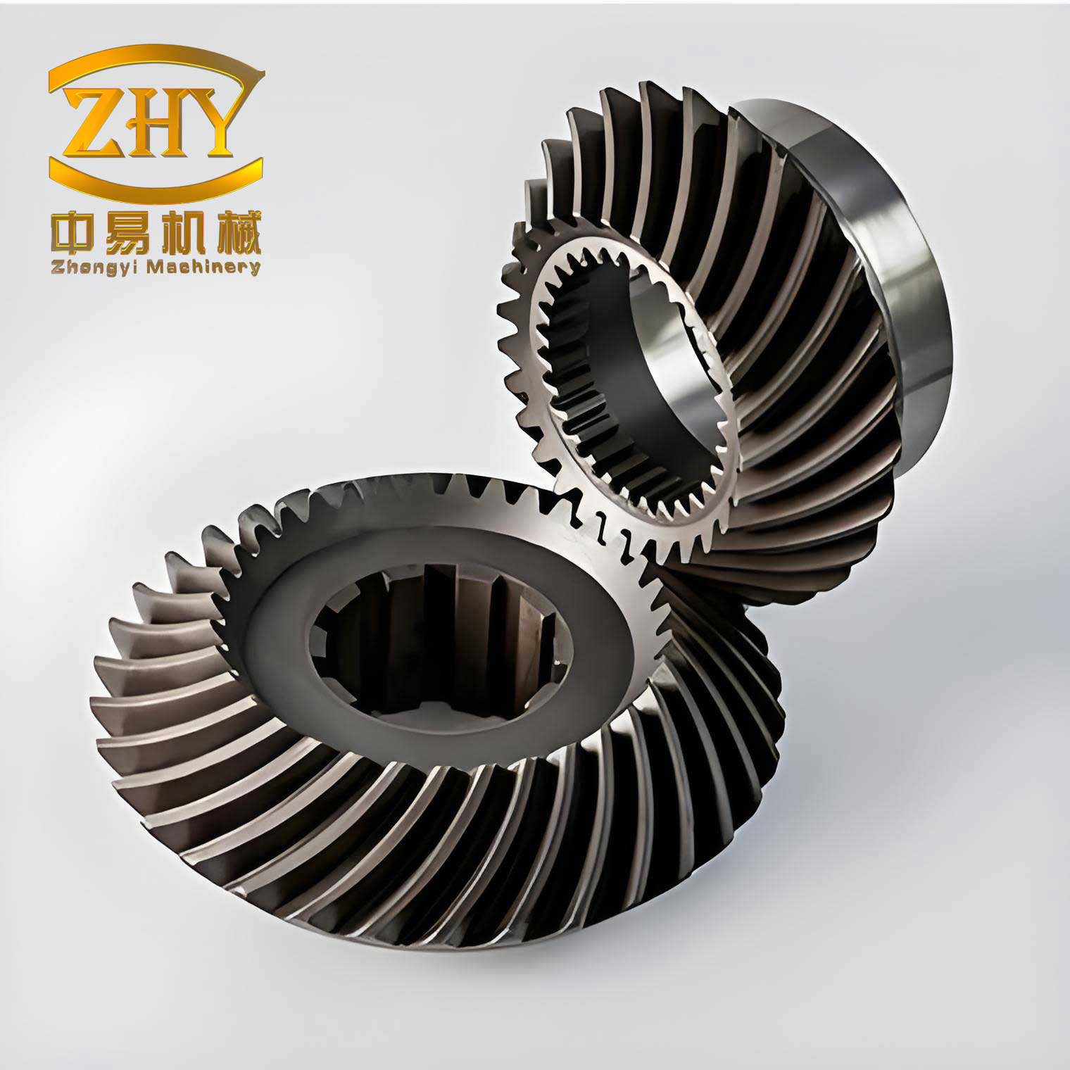
The inspection of the contact pattern is typically conducted on a rolling tester, where I examine its position, size, and shape. By altering the installation positions of the spiral bevel gears, different contact conditions can be observed. Through repeated adjustments and inspections, I have summarized the variation patterns and used these to debug and modify the machining process parameters. In practice, I first adjust the tester to the theoretical installation distance using gauge blocks, install and fix the gear pair to be inspected, and restore the spindle boxes to their predetermined positions based on dials or scales. Since observing the contact pattern on the large gear tooth flank is more convenient and clear during cutting adjustments, and adjusting the pinion contact pattern is more efficient for production, I primarily focus on the large gear contact pattern during inspections but use the pinion’s contact pattern variation as the basis for machine adjustments. To facilitate this, I apply a thin layer of red lead to the pinion teeth; after meshing and operation, the contact pattern becomes easily identifiable. The machine is then operated for 30 seconds in one direction and 30 seconds in the reverse direction, and based on the contact points obtained, I judge the contact pattern position. From this inspection method, I have derived the variation patterns for a left-hand pinion when changing the relative positions of the two spindles on the tester, as summarized in Table 1.
| Adjustment | Contact Pattern Movement in Height Direction | Concave Flank Movement in Length Direction | Convex Flank Movement in Length Direction |
|---|---|---|---|
| Increase installation distance (+ΔH) | Moves from tip to root (significant effect) | Moves toward small end (minor effect) | Moves toward large end (minor effect) |
| Decrease installation distance (-ΔH) | Moves from root to tip (significant effect) | Moves toward large end (minor effect) | Moves toward small end (minor effect) |
| Positive offset (+ΔV) | Moves from tip to root (minor effect) | Moves from large end to small end (significant effect) | Moves from small end to large end (significant effect) |
| Negative offset (-ΔV) | Moves from root to tip (minor effect) | Moves from small end to large end (significant effect) | Moves from large end to small end (significant effect) |
Note that for a right-hand large gear, the variation patterns are consistent with Table 1, but the signs of ΔH and ΔV are opposite. For a right-hand pinion, the contact pattern movement in the length direction is opposite to that of a left-hand pinion, while the height direction movement remains the same. These patterns are crucial for understanding how to adjust spiral gear contact patterns effectively.
In production, contact pattern deviations can occur due to new product development, tool breakage and replacement, or operator changes between shifts. To correct these deviations, I have developed several methods based on practical experience. The correction of the contact pattern involves adjustments in the length direction, height direction, diagonal contact, and width, each requiring specific techniques and parameter changes.
Correction of Contact Pattern in the Length Direction
The position of the contact pattern in the length direction is closely related to the spiral angle of the spiral gear. From the definition of spiral angle, the slope in the length direction is tied to the tooth flank spiral angle, making this one of the few clear relationships in spiral gear contact pattern correction. The contact pattern movement toward the large or small end is caused by errors in the spiral angle. Correction is generally achieved by changing the radial cutter position to alter the gear’s spiral angle, while also checking factors such as horizontal and vertical wheel positions and cutter diameter to ensure accuracy.
In adjustment, if the spiral angle needs to be increased, the radial cutter position is decreased; conversely, if the spiral angle needs to be decreased, the radial cutter position is increased. This can be expressed mathematically: let $\beta$ be the spiral angle and $R_c$ be the radial cutter position, then for a small change, $\Delta \beta \propto -\Delta R_c$. Typically, for equal-height teeth, the cutter position change ranges from 0.1 to 0.6 mm, but for larger changes, it should be calculated based on the ΔV value determined from the rolling tester. The relationship can be approximated as:
$$
\Delta R_c = -k \cdot \Delta \beta
$$
where $k$ is a constant dependent on gear geometry. It is essential to verify the machine’s direction before making adjustments. Table 2 summarizes the effects of changing various factors on the contact pattern.
| Change Factor | Contact Pattern Change on Concave Flank | Contact Pattern Change on Convex Flank |
|---|---|---|
| Decrease radial cutter position or eccentric angle | Moves from small end to large end | Moves from large end to small end |
| Increase radial cutter position or eccentric angle | Moves from large end to small end | Moves from small end to large end |
Correction of Contact Pattern in the Height Direction
The position of the contact pattern in the height direction is determined by the slope in the height direction, which depends on the pressure angle of the tooth profile. Contact pattern bias toward the root or tip is caused by pressure angle errors. Correcting the height direction position involves adjusting the pressure angle. This often occurs simultaneously with spiral angle errors, and I use two main methods:
- For small pressure angle corrections: Change the cradle center position. If the contact pattern is biased toward the tip (tip contact), decrease the cradle center position and increase the bed position; if biased toward the root (root contact), increase the cradle center position and decrease the bed position. This can be represented as:
$$
\Delta P_c \propto -\Delta \alpha, \quad \Delta B \propto \Delta \alpha
$$
where $\Delta P_c$ is the change in cradle center position, $\Delta \alpha$ is the pressure angle change, and $\Delta B$ is the bed position change. - For large pressure angle corrections: Change the transmission ratio (roll ratio). To correct tip contact on the pinion, increase the machine roll ratio; to correct root contact, decrease the roll ratio. This can correct pressure angle errors by 2° to 3°. The relationship is:
$$
\Delta i \propto \Delta \alpha
$$
where $\Delta i$ is the change in roll ratio.
Correction of Diagonal Contact
Diagonal contact primarily arises due to the use of the flat-top gear processing principle during cutting, where the spiral angle and pressure angle vary along the tooth length. On the convex flank, the pressure angle is smaller at the large end and larger at the small end, while the concave flank is opposite, leading to a tendency for the contact pattern to run from the small end root to the large end tip on the convex flank (inner diagonal) and vice versa on the concave flank. Additionally, improper nominal cutter diameter selection or disordered adjustment data can cause diagonal contact. For minor diagonal contact, it may self-correct through running-in, but for significant cases, I apply the “roll ratio – horizontal wheel position” method, simultaneously adjusting the bed position to maintain cutting depth and the cutter position to ensure proper contact pattern location along the tooth length. Table 3 outlines the corrections for diagonal contact.
| Correction Object | Flank Type | Radial Cutter Position Change | Axial Wheel Position Change | Bed Position Change |
|---|---|---|---|---|
| Outer Diagonal Contact | Convex | Increase | Decrease | Decrease |
| Concave | Decrease | Increase | Increase | |
| Inner Diagonal Contact | Convex | Decrease | Increase | Increase |
| Concave | Increase | Decrease | Decrease |
Alternatively, diagonal contact can be corrected by changing the additional rolling mode or vertical wheel position (hypoid offset). These adjustments help align the contact pattern properly on the spiral gear tooth surface.
Adjustment of Contact Pattern Width
The width of the contact pattern is commonly adjusted by changing the vertical wheel position. This affects the curvature of the gear tooth surface, thereby influencing the contact pattern width. Table 4 shows the effects of vertical wheel position adjustments on the contact pattern width for different spiral gear configurations.
| Gear Type | Flank Type | Vertical Wheel Position Movement | Cradle Position Change | Roll Ratio Change | Contact Pattern Width Change |
|---|---|---|---|---|---|
| Left-Hand | Convex | Upward | Decrease | Increase | Increases |
| Concave | Downward | Increase | Decrease | Increases | |
| Right-Hand | Convex | Downward | Decrease | Increase | Increases |
| Concave | Upward | Increase | Decrease | Increases |
The relationship between vertical wheel position change and contact pattern width can be described by:
$$
\Delta W \propto \Delta V_w
$$
where $\Delta W$ is the change in contact pattern width and $\Delta V_w$ is the change in vertical wheel position. This adjustment is vital for optimizing the load distribution and performance of spiral gears.
In conclusion, the methods I have described for spiral gear contact pattern adjustment require practical analysis based on specific situations. Typically, when the contact pattern deviates, comprehensive adjustments involving multiple parameters are necessary. Through hands-on experience, I have learned to combine these adjustments effectively to achieve desired results. The contact pattern is a key parameter for spiral gears, and mastering its inspection and correction techniques is essential for improving yield rates and enhancing overall efficiency in manufacturing. By continuously summarizing and refining these methods, I ensure that spiral gear systems meet high-quality standards, contributing to reliable and durable gear applications in various industries. The use of rolling testers, combined with mathematical models and empirical data, allows for precise control over spiral gear performance, making these gears indispensable in advanced mechanical transmissions.