
In order to study the feasibility of two-degree-of-freedom tooth turning of helical gear, the installation and layout relationship between the tooth turning cutter, the imaginary shape-producing wheel and the helical gear is first established, and the meshing motion in the tooth turning of helical gear is analyzed, and then the theoretical model of tooth turning of helical gear is constructed.
The installation layout of turning helical gear with straight tooth turning tool is shown in Figure 1. The three gears are in point contact at each instant and mesh at the same point. In the direction of tooth line at the contact point, there is relative movement between the turning tool and the helical gear, which is the prerequisite for realizing the turning of helical gear. The straight cylindrical gear in the figure is made into a straight tooth turning tool by pulling out the front and rear cutting surfaces, so that the point on the front cutting edge of the turning tool falls on the contact point of the imaginary generation wheel and the spiral tooth surface gear mesh. When the gear turning tool and the workpiece do forced meshing movement, it will cut a small section of material on the evenly distributed position of the workpiece, so that the tool and the workpiece complete the same forced meshing movement at each position, forming a complete tooth surface.
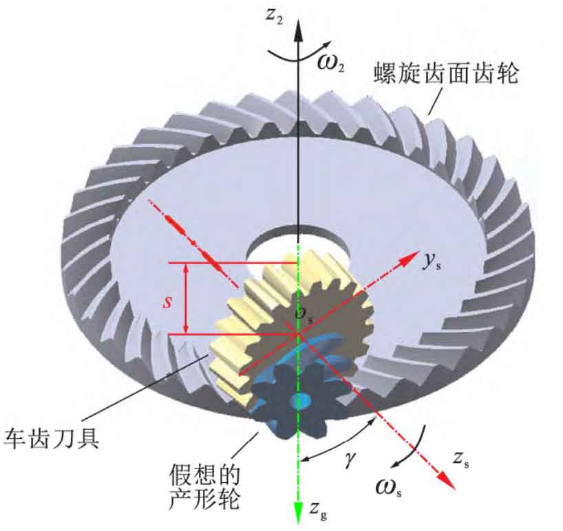
Based on the installation layout in Figure 1, the imaginary profile wheel axis is orthogonal to the helical gear axis, and the axis of the tooth turning tool and the imaginary profile wheel axis are inclined to each other by an angle (shaft intersection angle γ) , It is related to the imaginary generating wheel and the helix angle of the tool. When the tool is a straight tooth tool, the helix angle is 0 °, so:

Where, β It is the imaginary spiral angle of the generating wheel.