
The overall error curve of helical gear is a complete error curve of helical gear, which is formed by measuring the error values of each point on all working tooth surfaces of a single helical gear with the same zero position and arranging them according to the actual meshing sequence of each point on the tooth surface.
On the overall error curve of helical gear, the error values of all error items of helical gear can be read, their change rules can be understood, and the compensation relationship, causal relationship and internal relationship among various errors can be analyzed. The purpose is to solve the shortage of helical gear transmission error in studying the dynamic characteristics and vibration noise of helical gear transmission. Analyzing the error curve of helical gear with the overall error theory can deeply understand the actual meshing process, transmission characteristics and the influence of helical gear design on transmission quality, so as to provide a scientific theoretical basis for evaluating the accuracy, transmission quality, processing technology and improving the design of helical gear.
During the meshing process of the driving and driven wheels, for any contact point on the driving tooth profile, the conjugate tooth profile corresponding to the driven wheel has a unique meshing point corresponding to it. The contact between the driving and driven gears at the conjugate point makes the overall error of their respective helical gears constitute the equivalent overall error of the helical gear pair at that time.
According to the structural characteristics and meshing principle of helical gear, the overall error curve of helical gear pair of two adjacent meshing tooth pairs is relatively independent, and the overall error curve of helical gear pair of single pair of teeth is the basic component of the overall error curve of helical gear pair. Therefore, the overall error curve of the gear pair of a single pair of helical gears is called the overall error curve of the unit helical gear pair, and its form is shown in the figure:
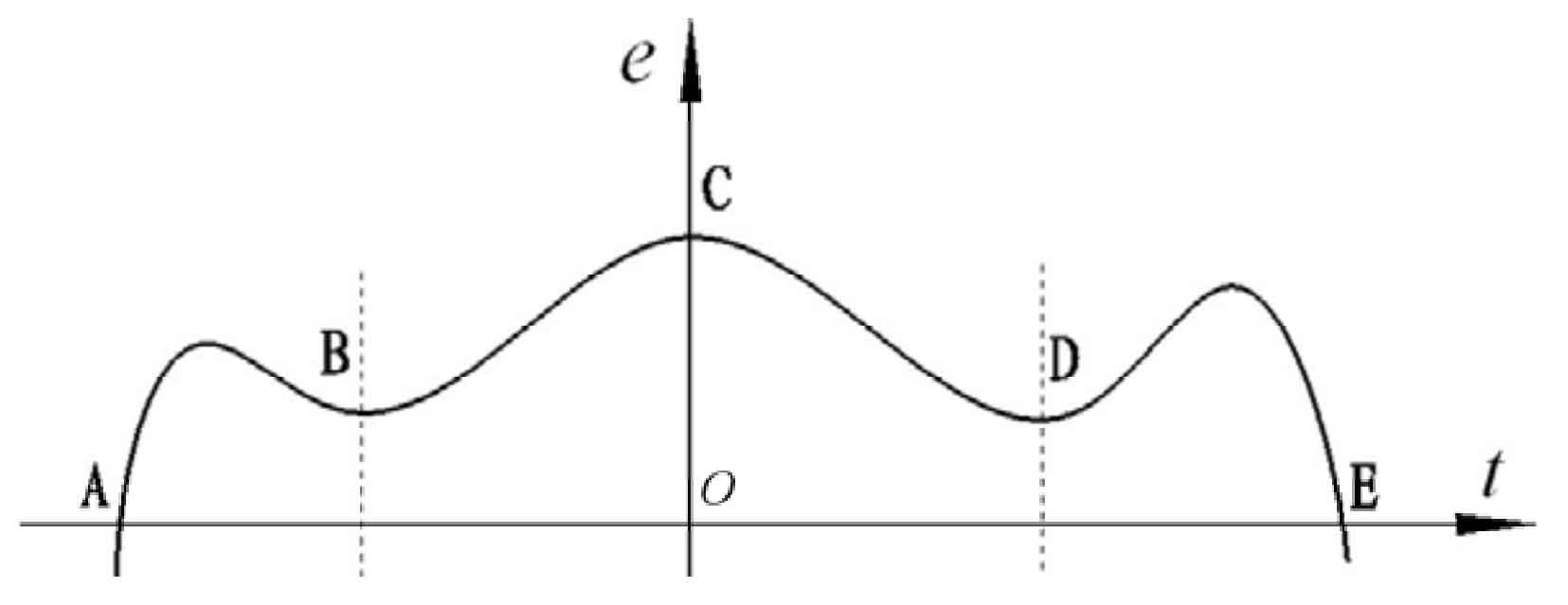
The overall error curve of the unit helical gear pair in the figure consists of three parts, in which ab is the error curve when the tooth top of the standard helical gear and the tooth root of the measured helical gear are engaged externally, also known as the top edge engagement error curve of the standard tooth profile. De is the error curve when the tooth top of the tested helical gear engages with the tooth root of the standard tooth profile outside the meshing line, which is called the top edge meshing error curve of the helical gear. BCD segment is the tooth profile error curve, which can be either the normal meshing tooth profile error curve or the end face involute error curve. The tooth profile error with positive pressure angle will cause negative base pitch deviation.