The automobile rack and pinion steering gear assembly is an important steering component of many automobiles. The automobile rack and pinion steering gear has many parts, and its main components are a pair of meshing steering gears and steering racks. Due to the limitation of space and the similar method of interface design of parts and components of automobile rack and pinion steering gear, this paper selects the main parts of automobile rack and pinion steering gear, steering gear and steering rack, and only introduces their interface design in detail.
(1) Gear interface design of automotive rack and pinion steering gear
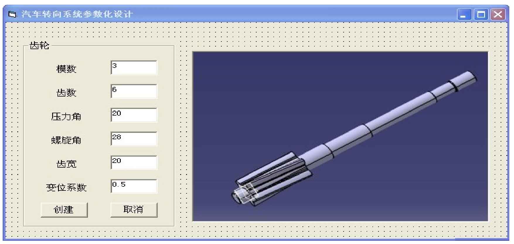
Add the form of automobile rack and pinion steering system in the VB software engineering module, add the labels and text boxes of parameters such as module, number of teeth, helix angle, pressure angle, tooth width and displacement coefficient of steering gear in the form of automobile steering system, input the parameters required by steering gear in the text box, and then add create and Cancel buttons and gear three-dimensional diagram. Click the Create button and input the required program to complete the gear interface design of the automobile rack and pinion steering system. The gear interface of the steering gear is shown in Figure 1.
(2) Design of rack and pinion steering gear interface
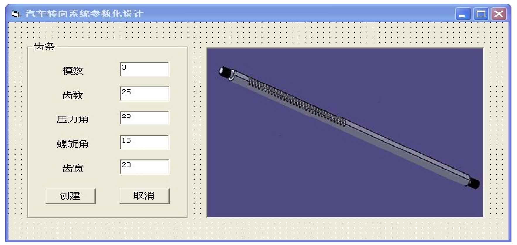
Similarly, add the automobile rack and pinion steering system window in the VB software engineering module, add the labels and text boxes of the parameters such as the modulus, number of teeth, helix angle, pressure angle and tooth width of the steering rack in the automobile rack and pinion steering system window, enter the parameters required by the steering rack in the text box, and then add the create and Cancel buttons and the three-dimensional diagram of the steering rack. Click the Create button and input the required program to complete the steering rack interface design. The rack interface of automobile rack and pinion steering gear is shown in Figure 2.


