
In order to meet the requirements of hobbing helical gear on the gear hobbing machine, the tooling fixture is designed according to the space conditions and structural dimensions of the gear hobbing machine, and the fixture shall meet the following requirements:
(1) The bevel gear blank should occupy the correct machining position in the fixture;
(2) The designed fixture shall be installed in an accurate position on the gear hobbing machine;
(3) The helical gear hob should have an accurate position relative to the designed fixture.
This set of fixture is designed for the face gear blank as shown in Figure 1. Nylon 6 is selected as the face gear blank material. Because nylon material has the characteristics of high mechanical strength, good toughness, outstanding fatigue resistance, good wear resistance, high hardness and easy processing, nylon 6 is selected as the face gear blank material. According to the actual machining situation of helical gear on hobbing machine, the positioning datum of workpiece is selected. Take the end face of the face gear blank as the positioning datum plane and the shaft hole as the positioning hole, complete the clamping of the face gear blank in the fixture, and determine the correct position of the workpiece in the fixture. This clamping method determines the unique position of the face gear blank, limits the six degrees of freedom of the face gear blank, and completely positions the face gear blank, that is, completes the final clamping of the face gear blank.
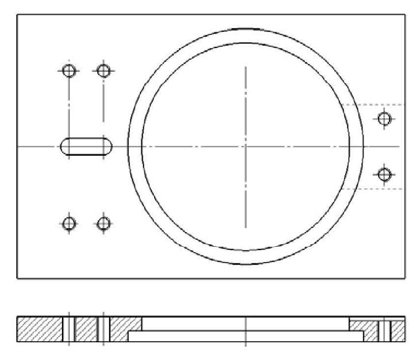
The fixture consists of three parts. First, determine the accurate position of the fixture on the machine tool. In order to realize the reliability and accuracy of workpiece processing, a fixed working plate is designed on the workbench, as shown in Figure 2. The purpose is to ensure the parallelism of the working plate relative to the worktable (i.e. to ensure that the end face of the working plate is horizontal). Assemble the designed bearing pedestal with the working. Slot on the working plate to ensure the perpendicularity of the groove bottom and side, and realize the accurate clamping of the working plate and the upper pressing plate.
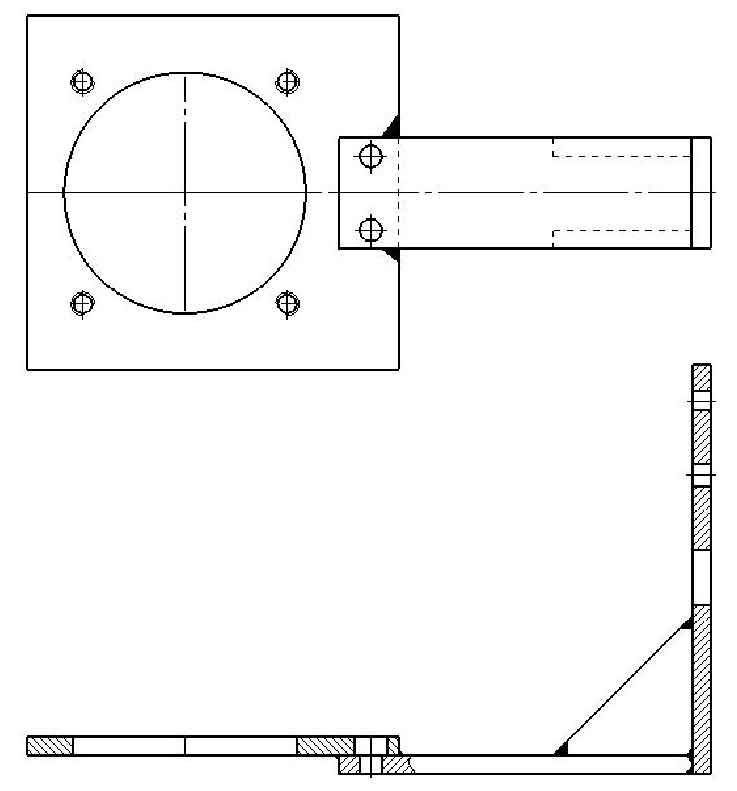
Secondly, determine the position of the upper pressing plate. According to the limitation of the spatial structure of the gear hobbing machine, another part of the clamp that meets the requirements in the processing process, the upper pressing plate, is designed, as shown in Fig. 3. In order to ensure the relative position accuracy and correct clamping between the upper pressing plate and the column of the gear hobbing machine and the working plate, strict requirements must be made on the position accuracy of the upper pressing plate. When welding the first part and the second part, ensure the perpendicularity of the bottom surface of the first part and the side of the second part, the parallelism of the two sides of the second part, and the perpendicularity of the bottom surface and the side.
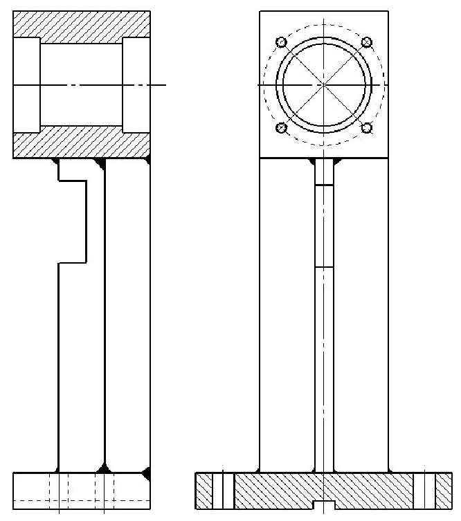
Third, ensure the accurate position of the bearing seat and the working plate during clamping, take the axis of the bearing hole and the bottom surface of the bearing seat as the benchmark, and ensure the perpendicularity of the keyway axis and the two. In order to realize the correct position of the shaft in the bearing hole, ensure the parallelism between the bearing hole and the bottom surface of the bearing seat, and prevent the inclination of the bevel gear blank installed on the shaft, so as to cause large error in the tooth shape after machining. Figure 4 shows the bearing seat.
When clamping the bearing seat, bearing and shaft, it is required to ensure that the shaft hole of the bearing seat is concentric with the bearing hole. The keyway at the bottom of the bearing seat is assembled with the key. A key needs to be fixed in the groove with a small screw, and then matched with the keyway of the working plate, and the center line of the keyway coincides with the center line of the working plate to ensure the accurate positioning of the bearing seat relative to the machine tool. In order to prevent the bearing seat from dislocation when machining the surface gear blank of helical gear hobbing, the bearing seat is fastened on the working plate with four hexagon screws, which effectively limits the 6 degrees of freedom of the bearing seat and completes the positioning and clamping of the bearing seat.
The clamping of the shaft is shown in Figure 5. Ensure the accurate clamping and positioning of the blank in the fixture and the correct position of the blank in the machine tool. The right end of the shaft is equipped with a pair of bevel gears with a transmission ratio of 1:1. The rotary motion and torque of the machine tool spindle are transmitted to the shaft matched with the bearing seat through bevel gear transmission. The shaft shoulder at the left end of the bevel gear is positioned, and the right end is clamped by a baffle and a screw. When the helical gear blank is hobbed, the blank mainly bears radial load but also axial load. According to the stress characteristics of the blank, a pair of tapered roller bearings are selected for assembly with the bearing seat. The bearing is installed back-to-back in order to make the shaft of the installation blank more stable, flexible and strong compensation ability. Bearing 18 is positioned through the shaft shoulder, the outer ring of bearing 7 is positioned through the shaft shoulder, and the inner ring is fastened with the lock nut through the stop washer. The purpose of using the stop washer is to prevent the nut from loosening during rotation.
Positioning and clamping of helical gear blank. The radial positioning of helical gear blank adopts shaft hole matching; Round nuts are used for axial positioning. When clamping the blank, first, a pressing plate is installed at the front and rear of the blank, and a U-shaped adjusting plate is installed at the left of the front pressing plate. In the design, the convenience of assembly and disassembly of the helical gear blank is considered, so that the shaft hole of the helical gear blank is larger than the outer diameter of the nut used. When clamping, the nut is used in combination with the U-shaped adjusting plate to facilitate the disassembly of the helical gear; After the processing of helical gear is completed, loosen the nut and remove the U-shaped adjusting plate to facilitate the disassembly and assembly of helical gear, so as to facilitate the disassembly and assembly during batch processing. Secondly, in order to ensure the accurate positioning of the helical gear blank in the fixture, the marking method is used to find the center position of the blank, so as to ensure that the helical gear blank does not move, the helical gear blank does not deform or the surface of the helical gear blank is not damaged during the machining process; Third, tighten the bevel gear blank with nuts. The clamping of helical gear blank is shown in Figure 5.