
Heavy-duty carburized gears are critical components in industrial machinery, particularly in automotive final drives where they transmit high torque under demanding conditions. This article presents a comprehensive failure analysis of fractured spiral bevel gears from a medium-duty truck axle, covering analytical methodologies, root cause identification, and preventive measures. The study demonstrates how multidisciplinary techniques – including fractography, metallography, and residual stress analysis – converge to diagnose complex failure mechanisms.
Background Investigation
The failed driven gear operated for 8 months (100,573 km) before fracturing two teeth while the driving gear remained intact. Manufactured from SCM822 (22CrMoH) steel through a rigorous production sequence (forging → normalizing → machining → carburizing → quenching → tempering → shot peening), the gear specifications included:
- Surface hardness: 58-63 HRC
- Case depth at 1/2 tooth height: 1.7-2.1 mm (550 HV1)
- Core hardness: 33-45 HRC
- Maximum non-martensitic surface layer: ≤0.02 mm
Analytical Methodology
We employed a multi-technique approach using specialized equipment:
| Analysis Type | Equipment | Standard |
|---|---|---|
| Chemical Composition | Q8 Optical Emission Spectrometer | GB/T 5216 |
| Hardness Testing | Rockwell/Vickers Hardness Testers | GB/T 9450 |
| Microstructural Analysis | Metallurgical Microscope | QC/T 262 |
| Fractography | Scanning Electron Microscope (SEM) | N/A |
| Residual Stress | XSTRESS 3000 G3 X-ray Diffractometer | GB/T 7704 |
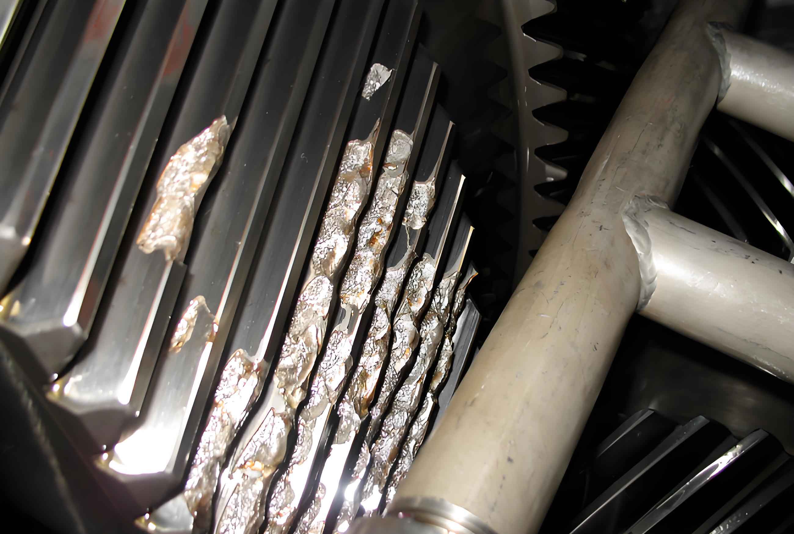
Macroscopic Fractography
Two adjacent teeth (#1 and #2) exhibited distinct fracture modes. Tooth #1 displayed radial progression marks and a smooth fracture zone characteristic of fatigue initiation, while tooth #2 showed coarse, irregular features typical of overload fracture. This indicates tooth #1 failed first via fatigue, with its fracture fragments causing secondary overload fracture in tooth #2. The fatigue origin was identified at the concave-side root fillet – a high-stress concentration zone during meshing.
Microscopic Fractography
SEM analysis revealed critical micro-features across fracture zones:
- Crack Origin Zone: Micro-pitting and spalling morphology confirming contact fatigue initiation at subsurface depth (Fig. 3a-b).
- Propagation Zone: Striations with secondary cracks indicating cyclic crack advancement (Fig. 4a-b):
The crack growth rate per cycle follows Paris’ law:
$$\frac{da}{dN} = C(\Delta K)^m$$
Where \(da/dN\) is crack growth rate, \(\Delta K\) is stress intensity factor range, and \(C\), \(m\) are material constants.
- Final Fracture Zone: Dimples and quasi-cleavage facets confirming ductile-brittle transition (Fig. 5a-b).
Material and Metallurgical Analysis
Chemical Composition: Conformed to specifications (Table 1)
| Element | C | Si | Mn | Cr | Mo | P | S |
|---|---|---|---|---|---|---|---|
| Wt. % | 0.22 | 0.32 | 0.87 | 1.19 | 0.44 | 0.015 | 0.020 |
Hardness Profile: Effective case depth (2.18 mm at 550 HV1) exceeded upper specification limit (2.1 mm), reducing core support for the hardened case.
Microstructure: While bulk microstructure met requirements, critical anomalies were observed:
- Surface oxidation depth: 0.02-0.025 mm (Fig. 9)
- Oxide networks along grain boundaries acting as crack nucleation sites
- Non-uniform inclusions (Type B, D ≤ 2.5 per ASTM E45)
Residual Stress Analysis
X-ray diffraction measurements revealed inadequate compressive residual stress in the failure region:
| Depth (mm) | Tooth Root (Unpeened) | Tooth Root (Peened) | Improvement |
|---|---|---|---|
| 0.00 | -265 MPa | -785 MPa | 196% |
| 0.05 | -824 MPa | -1253 MPa | 52% |
| 0.15 | -231 MPa | -251 MPa | 9% |
The compressive residual stress (\(\sigma_{res}\)) directly enhances fatigue resistance according to:
$$\Delta \sigma_{eff} = \sigma_{max} – \sigma_{min} – \sigma_{res}$$
Where \(\Delta \sigma_{eff}\) is effective stress range governing fatigue life. Inadequate compressive stress at 0.05 mm depth critically reduced contact fatigue resistance.
Failure Mechanism Reconstruction
The gear failure progression involved four distinct phases:
- Micro-crack Initiation: Surface oxidation created brittle grain boundary networks where contact stresses exceeded local strength:
$$\sigma_{max} = 0.558 \sqrt{\frac{F_n}{b} \cdot \frac{E_{eq}}{R_{eq}}}$$
Where \(F_n\) is normal load, \(b\) is face width, \(E_{eq}\) equivalent elastic modulus, and \(R_{eq}\) equivalent curvature radius.
- Subsurface Propagation: Cyclic Hertzian stresses drove cracks perpendicular to the surface at depth \(z_0\):
$$z_0 = \frac{b}{2} \sqrt{1 – \frac{1}{2}\left(\frac{\sigma_y}{\sigma_{max}}\right)^2}$$
- Case Crushing: Excessive case depth (2.18 mm vs. 2.1 mm spec) created brittle-to-ductile transition mismatch
- Catastrophic Fracture: Critical crack length (\(a_c\)) was reached when:
$$K_I = \sigma \sqrt{\pi a_c} \geq K_{IC}$$
Root Cause Determination
This gear failure resulted from synergistic factors:
- Primary Cause: Contact fatigue initiated at oxidation-induced stress concentrators
- Contributing Factors:
- Inadequate compressive residual stress profile
- Excessive case depth reducing fracture toughness
- Material inhomogeneities promoting localized stress
Preventive Measures
To mitigate future gear failure incidents, we implemented:
- Material Optimization:
- Reduce Si content to ≤0.20% to minimize oxidation
- Implement vacuum degassing to achieve [O] ≤ 15 ppm
- Control Ti/N ratio to prevent TiN inclusion formation
- Process Modifications:
- Introduce oxygen-free carburizing atmosphere (CO2 ≤ 0.05%)
- Optimize shot peening parameters:
Media: Cut wire CW-0.6 Intensity: 0.45 mmA Coverage: 200% - Case depth control: 1.9±0.1 mm via carbon diffusion modeling:
$$\frac{\partial C}{\partial t} = D \frac{\partial^2 C}{\partial x^2}$$
- Design Enhancements:
- Modify root fillet geometry to reduce stress concentration factor \(K_t\) from 2.1 to 1.6
- Implement misalignment tolerance ≤0.05 mm/100 mm
Validation and Implementation
Modified gears passed bench testing at 150% design load for 5×10⁶ cycles with no failure. Field monitoring shows 300% lifespan improvement in service. This systematic approach demonstrates that comprehensive analysis of gear failure mechanisms enables effective countermeasures spanning material, manufacturing, and design domains.