
Take spur gear as an example to analyze hobbing kinematics, as shown in the figure.
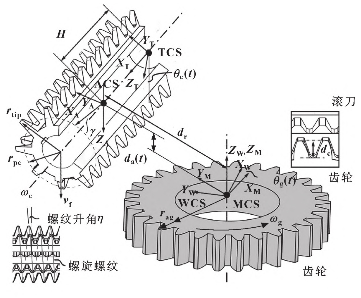
Hob (cutter) and spur gear (workpiece) rotate around its axis at angular speed ω C and ω G Synchronous rotation. The hob feeds along the width of the spur gear at the axial feed speed vf, and the axial displacement is da. Inclined rotation angle of hob shaft γ, To effectively mesh the tool with the spur gear. For tools and spur gears with the same rotation direction, γ The definition is as follows:
Where: β Is the helical angle of spur gear; η Is the angle rise of hob thread.
Angular speed of spur gear to be machined ω G is selected according to the number of workpiece teeth and the number of hob thread heads:
Where: Ng is the number of workpiece teeth; Nc is the number of hob thread heads; Mn is the normal modulus of spur gear; σ = sgn β· sgn η· Sgnvf, is the correction parameter.
The rising angle of hob thread is determined by η = Arcsin (mnNc/2rpc), where rpc is the pitch radius of the hob. Generally, the cutting depth in gear hobbing is set to dc=2 25 mn 。 At the beginning of the machining operation, the hobbing center distance dr is set as follows:
Where: rtip is the radius of spur gear hob tip; Rag is the addendum radius. In the tool coordinate system (TCS), a point along the hob edge can be represented by the vector rc (t). According to the needs of the three-way Dexel model, the same point can also be expressed as rw (t) in the Workpiece Coordinate System (WCS). In addition, two additional coordinate systems are defined: Machine Coordinate System (MCS) and Auxiliary Coordinate System (ACS). MCS is stationary and shares a common origin and Z axis with WCS. The ACS at the midpoint of the hob is parallel to the MCS. The homogeneous transformation connecting rc and rw can be expressed as:
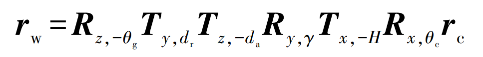
Where: Rz, – θ G represents the rotation angle of spur gear around its Z axis θ g; Ty, dr refers to the translation dr of the hob along the Y axis of ACS; Tz, – da indicates the axial feed da of the hob along the Z axis of ACS; Ry, γ Indicates the rotation angle of the hob around the Y axis of ACS γ; Rx, θ C indicates the hob rotates around its X axis θ c; Tx, – H represents the axial displacement H of hob translation along its X axis.