
Abstract:
This paper focuses on the kinematics analysis and machining simulation of bevel gear milling machines. By examining the transmission system of a mechanical bevel gear milling machine, the relative motion relationships among the cutter, cradle, work gear, and generating gear during the gear cutting process are derived. These relationships lead to the generalization of the motion control principles for bevel gear milling machines. Utilizing these principles, a cutting simulation platform for bevel gears is built in the VERICUT software, enabling the simulation of the manufacturing process for a specific bevel gear pair.
1. Introduction
Bevel gears are crucial transmission components in various machinery systems, such as agricultural machinery, vehicles, airplanes, machine tools, and industrial reducers, transmitting motion and power between intersecting and offset shafts. They can be classified into arcuate tooth and epicycloid tooth types. Arcuate tooth bevel gears are typically manufactured using a five-cutter method, requiring cutter retraction and tooth division after each tooth is cut. In contrast, bevel gears are produced using face hobbing, a continuous process where both the concave and convex surfaces of the gear are rough-cut and finish-cut in a single operation.
As understanding of bevel gears has deepened, their high efficiency and smooth meshing characteristics have been recognized by the industry, leading to their increased use, particularly in vehicles with high noise requirements such as cars, buses, and vans. However, domestic research on face hobbing technology for bevel gears is insufficient, and no domestic milling machines for such gears have been developed, hindering their localization process in China.
This paper aims to address this issue by analyzing the motion laws of bevel gear milling machines and constructing a machining simulation platform using the VERICUT software. This research will contribute to the development of domestic bevel gear milling machines.
2. Kinematics Analysis of Bevel Gear Milling Machines
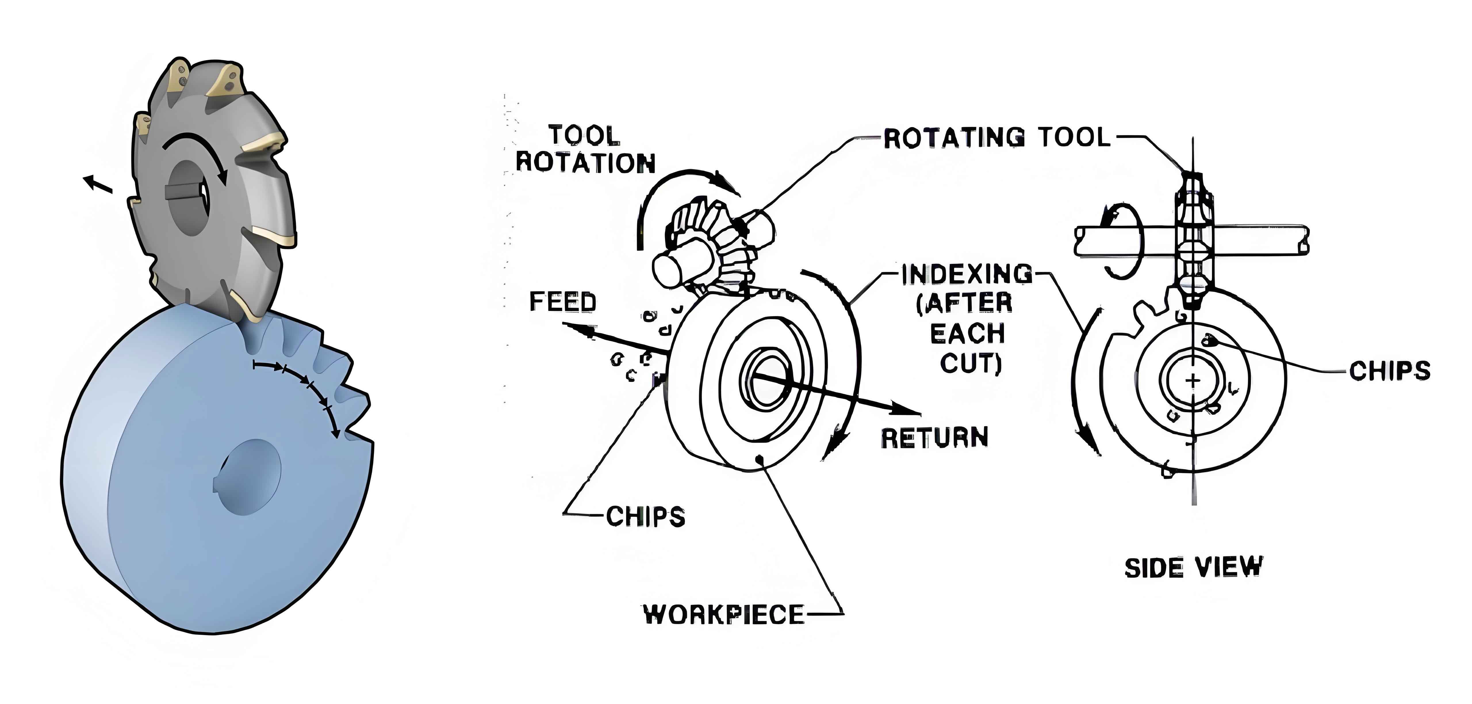
The process of manufacturing bevel gears can be seen as the meshing transmission between the generating gear and the work gear. The milling cutter typically has multiple sets of cutting teeth, with at least two teeth per set—an outer tooth (A) for the concave surface and an inner tooth (I) for the convex surface. As the milling cutter rotates through one set of teeth, the work blank and generating gear rotate by one tooth, producing the concave and convex surfaces of the gear tooth slot.
The rotation of the milling cutter and workpiece are coordinated with a specific transmission ratio, enabling continuous indexing of the gear during the cutting process. Simultaneously, the cutting teeth of the milling cutter form a long-amplitude epicycloid tooth line shape on the generating gear.
The main difference between bevel gear milling machines and arcuate tooth bevel gear milling machines lies in continuous indexing, which complicates the motion of these machines. Therefore, the key to analyzing their motion laws is to identify the relative motion relationships among the cutter, cradle, workpiece, and generating gear during the cutting process.
Table 1: Transmission System Components and Notations
| Symbol | Description |
|---|---|
| O | Milling cutter |
| P | Imaginary crown wheel |
| B | Work blank |
| H | Cradle |
| h | Differential gear case |
| W | Differential exchange gear |
| T | Indexing exchange gear |
| ωi | Rotational speed at location i |
The transmission system of a mechanical bevel gear milling machine can be simplified. The rotational speeds and transmission ratios of various components are derived using equations, considering the gear ratios and differential gearing.
3. Motion Realization in Fully Numerical Control Bevel Gear Milling Machines
The above analysis pertains to mechanical machines. In fully numerical control (CNC) milling machines, the cradle’s motion is replaced by the coordinated movement of a cross-slide. Therefore, no differential gearing exists between the milling cutter and cradle, and the absolute rotational speed of the milling cutter (ω’O) is equal to its rotational speed (ωO).
In CNC machines, the motion of each part of the machine is driven by separate motors. Therefore, the synthesis of the workpiece motion is accomplished through the electrical system. For simplicity, the workpiece spindle can be decomposed into two virtual spindles (A1 and A2). Virtual spindle A1 is related to the cradle speed, while virtual spindle A2 is related to the milling cutter speed.
Table 2: Comparison of Mechanical and CNC Bevel Gear Milling Machines
| Feature | Mechanical Machine | CNC Machine |
|---|---|---|
| Cradle & Milling Cutter Interaction | Differential gearing for motion synthesis | Separate motors for independent motion |
| Virtual Spindles | Not applicable | A1 (related to cradle speed) & A2 (related to cutter speed) |
| Motion Control | Mechanical linkage | Electrical system with electronic gearbox |
4. Establishment of Machining Simulation Platform
To verify the derived motion laws, a CNC machining simulation platform for bevel gear milling machines was constructed using the VERICUT software. The machine model includes an X-axis for column movement, a Y-axis for slide movement, a C-axis for milling cutter rotation, a Z-axis for cutting depth control, and a B-axis for adjusting the root cone angle.
The tool used in bevel gear cutting is a face milling cutter with multiple sets of teeth, each set consisting of roughing, inner finishing, and outer finishing teeth. However, since VERICUT cannot create such specialized tools, the complex face milling cutter was simplified for simulation purposes. Each cutting tooth was analyzed, and its cutting edge, which is a straight line with a certain pressure angle, was replaced by the generatrix of a cone-shaped milling cutter.
5. Machining Simulation Experiment
A cutting simulation experiment was conducted using the constructed simulation platform for a pair of 9×40 epicycloid hypoid gear sets. The basic geometric parameters and machine adjustment parameters for the gear sets are summarized in Tables 3 and 4, respectively.
Table 3: Basic Parameters of Epicycloid Hypoid Gear Sets
| Parameter | Small Gear | Large Gear |
|---|---|---|
| Number of Teeth | 9 | 40 |
| Module (mm) | 11.40 | |
| Shaft Angle (°) | 90 | |
| Offset Distance (mm) | 44.45 | |
| Midpoint Helix Angle | 46°30′ | |
| Face Width (mm) | 76.74 | 70.00 |
| Helix Direction | Left | Right |
| Average Pressure Angle | 22° |
Table 4: Machine Adjustment Parameters
| Parameter | Adjustment Value |
|---|---|
| Root Cone Angle | 16°31′ |
| Horizontal Wheel Position (mm) | -0.3219 |
| Vertical Wheel Position (mm) | 44.45 |
| Bed Position (mm) | 2.0 |
| Radial Tool Position (mm) | 245.4 |
| Roll Ratio | 4.5555556 |
| Cutter Tip Diameter (mm) | 200.00 |
| Inner Tooth Profile Angle | 20°3′ |
| Number of Cutter Sets | 17 |
Before processing, cone-shaped milling cutters were constructed based on the tooth pressure angle and positioned on the C-axis (milling cutter) according to the cutter radius. The work blank was then constructed based on its geometric parameters and placed in a fixed position on the A-axis. The cutting program was written based on the motion relationships among the milling cutter, cradle, and work blank, controlling the movement of each coordinate axis to complete the cutting process.
6. Conclusion
This paper analyzed the transmission system of a mechanical bevel gear milling machine, derived the relative motion relationships during the cutting process, and summarized the general motion control principles for such machines.