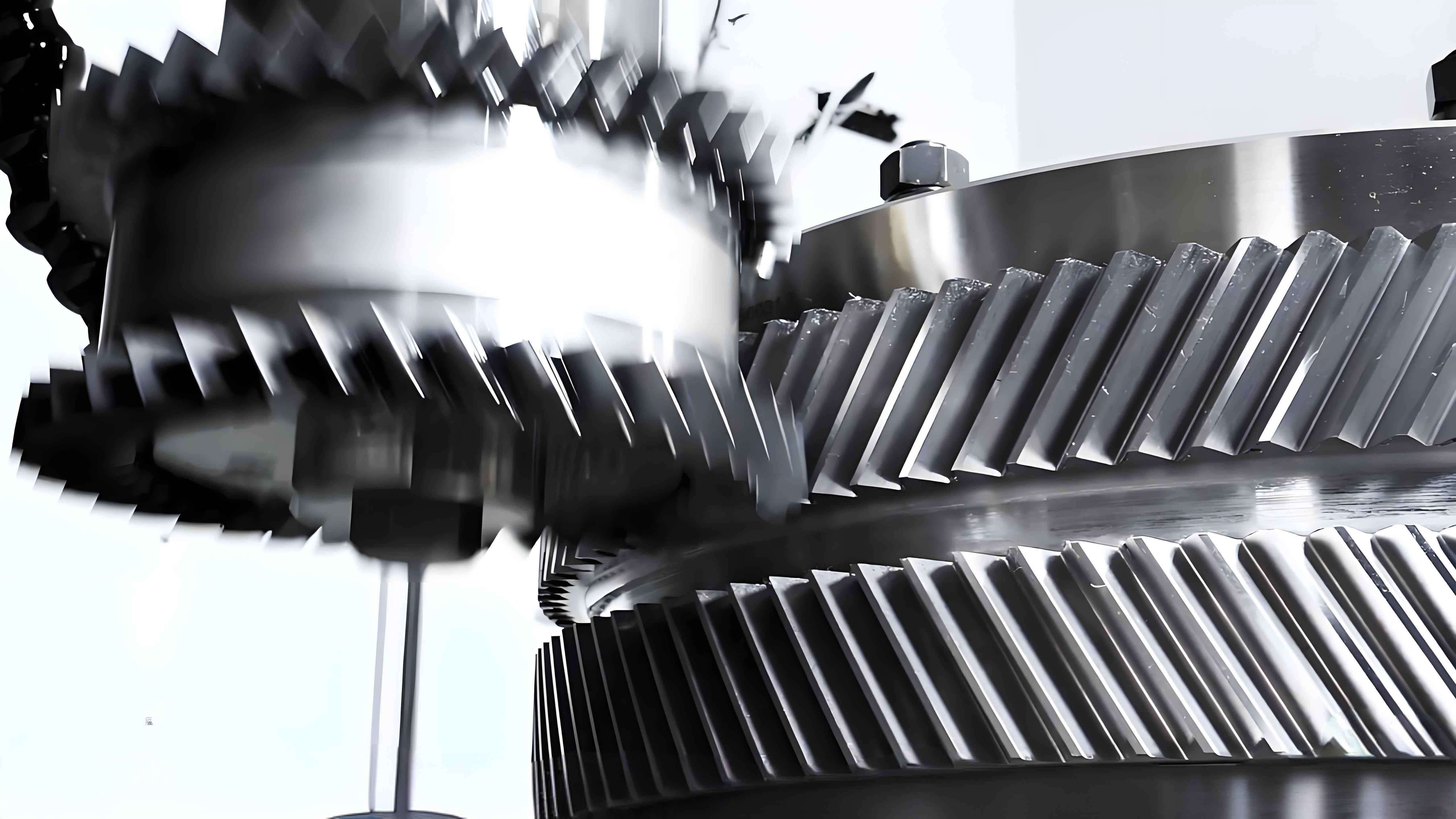
Herringbone gears are widely used in heavy machinery, aviation, and marine applications due to their high load capacity, compact structure, and balanced axial forces. However, asymmetric tooth pitch deviations caused by manufacturing and assembly errors significantly affect their dynamic performance. This paper proposes a comprehensive methodology to analyze the three-dimensional vibration characteristics of herringbone gears under asymmetric pitch deviations.

1. Mathematical Modeling of Asymmetric Pitch Deviations
The relative pitch deviation along the normal meshing line is expressed as:
$$ \lambda = (F_{pt1} – F_{pt2}) \cos\beta_b \cos\alpha_t $$
where $F_{pt1}$ and $F_{pt2}$ represent cumulative pitch deviations of pinion and gear, respectively. The periodic characteristics are determined by:
$$ T_l = T_m \cdot \text{lcm}(Z_1, Z_2) $$
Typical herringbone gear parameters and measured pitch deviations are shown in Table 1.
| Parameter | Pinion | Gear |
|---|---|---|
| Number of teeth | 17 | 44 |
| Normal module (mm) | 6 | 6 |
| Helix angle (°) | 24.43 | -24.43 |
| Face width (mm) | 55 | 55 |
2. Loaded Tooth Contact Analysis Model
The modified displacement coordination equation considering asymmetric deviations is:
$$ -\mathbf{F}_k\mathbf{p}_k + \mathbf{e}Z + \mathbf{I}\mathbf{d}_k + \mathbf{A}\delta_p = \mathbf{w}_k + \lambda_k $$
Where $\mathbf{F}_k$ is the flexibility matrix and $\delta_p$ represents axial displacement. The meshing stiffness for left/right helical pairs is calculated as:
$$ k_{m1} = \frac{T}{r_{p2}\cos\alpha_n\cos\beta (Z – \delta_{TE1})} $$
$$ k_{m2} = \frac{T}{r_{p2}\cos\alpha_n\cos\beta (Z – \delta_{TE2})} $$

3. Dynamic Model Formulation
The 3-D dynamic equations for herringbone gear system are established as:
$$ m_{1L}\ddot{x}_{1L} + c_{x1L}\dot{x}_{1L} + k_{x1L}x_{1L} + F_{nLx} + f_{s1}(t)\cos\beta_{bL}\sin\psi_{12L} = 0 $$
$$ I_{1L}\ddot{\theta}_{1L} + c_{t1}(\dot{\theta}_{1L} – \dot{\theta}_{1R}) + k_{t1}(\theta_{1L} – \theta_{1R}) + (F_{nL} + f_{s1}(t))r_{b1L}\cos\beta_{bL} = T_{1L} $$
Key dynamic parameters are summarized in Table 2:
| Parameter | Pinion | Gear |
|---|---|---|
| Mass (kg) | 7.11 | 64.75 |
| Support stiffness (N/m) | 2.42×10⁸ | 3.83×10⁸ |
| Torsional stiffness (Nm/rad) | 9.61×10⁶ | 6.13×10⁸ |
4. Vibration Characteristics Analysis
The 3-D vibration response shows distinct spectral features:
$$ a_{12L} = (\ddot{x}_{1L} – \ddot{x}_{2L})\sin\psi_{12L} + (\ddot{y}_{1L} – \ddot{y}_{2L})\cos\psi_{12L} + (r_{b1L}\ddot{\theta}_{1L} + r_{b2L}\ddot{\theta}_{2L}) $$

Key observations from numerical simulations:
- Shaft frequency components dominate displacement spectra
- Meshing frequency harmonics show amplitude increases with load (8.5 dB increase from 828 Nm to 5000 Nm)
- Axial vibration RMS exceeds tangential components below 2300 rpm
5. Asymmetric Meshing Impact Effects
The impact force calculation reveals significant differences between left/right pairs:
$$ f_s = \left( \frac{c+1}{2} \frac{I_1I_2}{I_1r_{b2}^2 + I_2r_{b1}^2} v_s^2k_s \right)^{c/(c+1)} $$
Dynamic load factors comparison under different speeds:
| Speed (rpm) | Left Side | Right Side |
|---|---|---|
| 2000 | 1.1267 | 1.1445 |
| 17200 | 1.4161 | 1.4597 |

6. Conclusion
This investigation reveals critical aspects of herringbone gear dynamics under asymmetric pitch deviations:
- Meshing frequency harmonics intensify with loading while sidebands attenuate
- Axial vibration components exhibit complex modulation patterns
- Asymmetric meshing impacts dominate vibration responses above critical speeds
- Dynamic load difference reaches 4.36% at 17200 rpm
The proposed methodology provides essential insights for optimizing herringbone gear design and vibration control in high-speed applications.
