Linear conjugate internal meshing gear transmission, also known as straight tooth conjugate internal meshing gear transmission, was first proposed by Swiss Paul Truninger for internal meshing gear pumps. In linear conjugate internal meshing gear transmission, the tooth profile of the outer gear is a straight line, while the tooth profile of the inner gear is a conjugate curve. Due to its small tooth profile curvature, high contact strength, and some special meshing characteristics, when used as a gear pair in internal meshing gear pumps, it can achieve the effect of small trapped oil volume, low flow pulsation, and low noise.
At present, research on linear conjugate internal meshing in China and abroad is mainly focused on the application of its gear pump. As a form of gear transmission, the research on its meshing principle and transmission performance is very insufficient, and there is still no complete standard for calculating tooth profile parameters. Therefore, its application scope is limited, and research on related meshing theories is also very rare.
In recent years, due to the excellent performance of the linear conjugate internal meshing gear pump gradually being recognized by the industry and promoted and applied in emerging technologies such as servo hydraulic systems, its product research and performance improvement have also been valued by enterprises, which has driven in-depth research on this special gear transmission. Many scholars have also begun to explore the application value of the linear conjugate internal meshing gear pair in the field of mechanical power transmission.
ZHY Gear defined the basic parameters of the linear tooth profile of the external gear and established the tooth profile coordinate equation by analyzing the meshing process and tooth profile parameters of the linear conjugate internal meshing gear pair. Based on this, a systematic analysis was conducted on the meshing limit point, pressure angle, meshing line, linear conjugate internal meshing gear transmission and its overlap degree on the tooth profile, and the relationship between the tooth profile segment and the corresponding meshing angle was studied, A tooth profile parameter design method was proposed to ensure continuous transmission conditions, and the tooth profile parameter design method and the meshing performance of linear conjugate internal meshing gear pairs were verified through engineering examples, which has certain significance for expanding its application fields.
1. External gear parameters and tooth profile equations
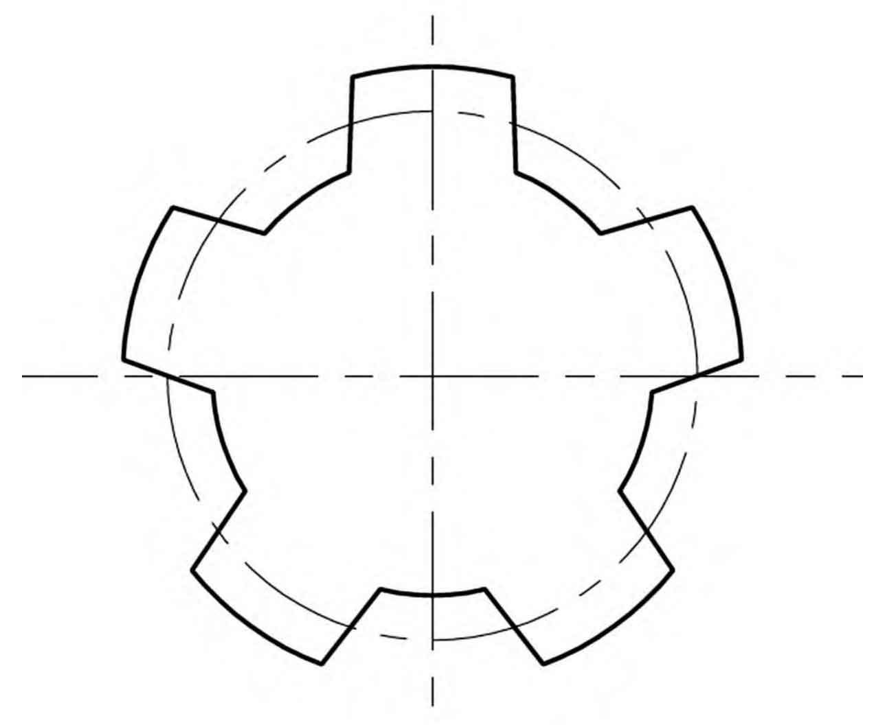
In a linear conjugate internal meshing gear pair, the tooth profile of the outer gear is a symmetrical straight line on both sides, and its tooth tip and tooth root are respectively circular arcs, as shown in Figure 1.
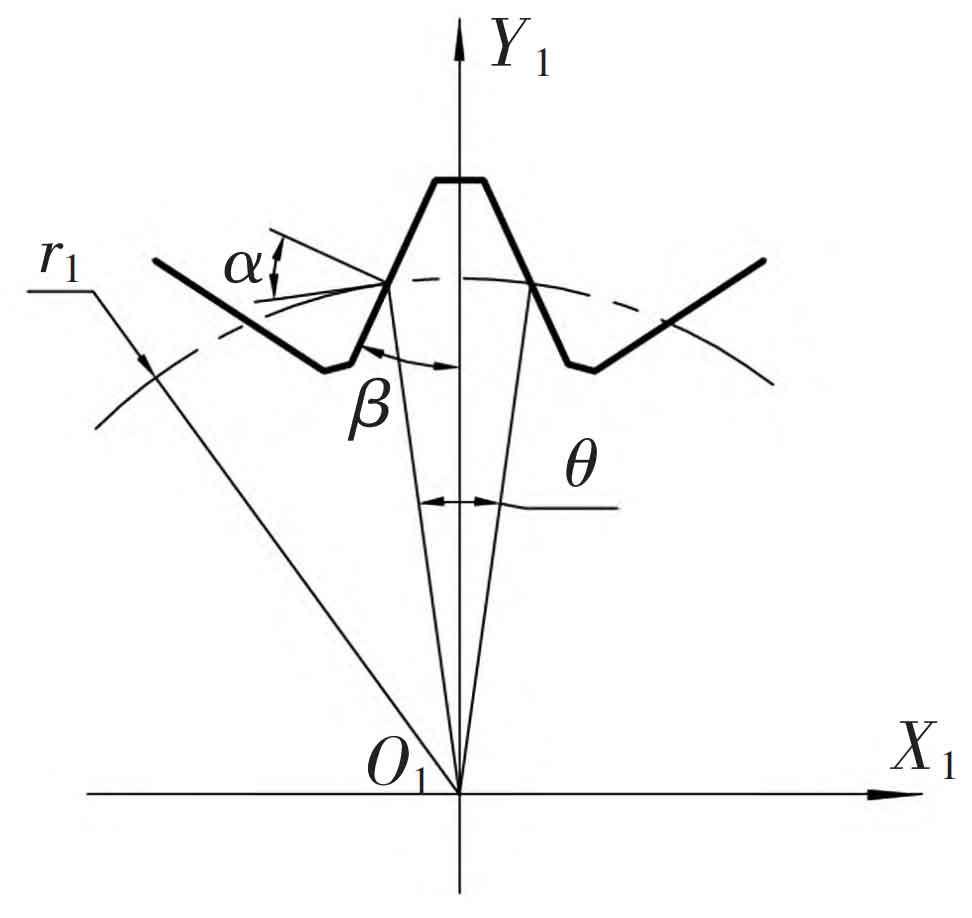
Establish a coordinate system O1X1Y1 with the center O1 of the external gear as the origin. The tooth profile equation of the external gear can be established through multiple geometric parameters, such as the tooth profile angle, indexing arc tooth thickness, and the distance between the tooth profile and the gear center. However, from an engineering practical perspective, for linear conjugate internal meshing gear pairs, using a parameter similar to the modulus of an involute gear for geometric calculation of the gear makes it easier for subsequent analysis and research, as well as performance comparison with involute gears.
In involute gears, the modulus is related to the indexing circle, and the pressure angle of the tooth profile curve on the indexing circle is specified as the standard value, which is an important feature of the indexing circle of involute gears. For standard involute gears, the indexing circle is located in the middle position of the tooth profile meshing area, which can effectively control the range of pressure angle changes during the meshing process and ensure the transmission efficiency of the gear. Similarly, the pressure angle on the straight tooth profile outer gear is also different at each point of the tooth profile, and the pressure angle also affects the transmission performance. Following the parameter settings of involute gears, the pressure angle on the indexing circle of the outer gear is defined as the standard pressure angle α, The formula for the tooth tip half angle is:
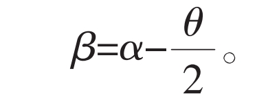
In the formula, θ The center angle corresponding to the tooth thickness s of the indexing circle of the external gear, without considering the meshing clearance, is specified that the tooth thickness s on the indexing circle of the external gear is equal to the tooth spacing e. Therefore:
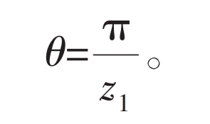
In the formula, z1 is the number of teeth on the external gear, then there is:
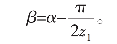
The visible tooth tip half angle is related to the number of teeth. When the pressure angle is constant, the smaller the number of teeth, the smaller the tooth tip half angle. The relationship between the two is shown in Figure 2.
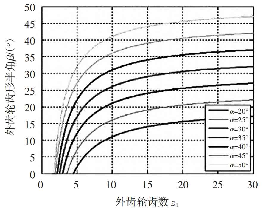
Due to β Cannot be negative, therefore for a given pressure angle, the gear will have a minimum number of teeth, such as when the pressure angle of the indexing circle is α At 20 °, the minimum number of teeth on the outer gear is 5, corresponding to the half angle of the tooth tip β At 2 °, the shape of the gear is shown in Figure 3.
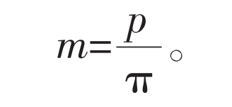
Using involute gears as a model to define the modulus, it serves as the basic parameter for linear profile external gears.
In the formula, p is the pitch of the external gear indexing circle.
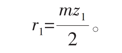
The linear equation of the left tooth profile of the gear is:
In the formula, r1 is the radius of the indexing circle of the external gear.

From equation (1), it can be inferred that the pressure angle at point k on the tooth profile of the external gear with a straight tooth profile is:
In the formula, θ K is the center angle corresponding to the thickness of the arc tooth passing through point k on the gear teeth.
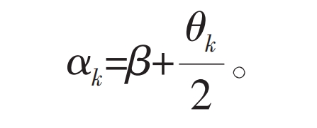
The pressure angle of the visible tooth profile decreases with the increase of radius. In theory, when the width of the tooth tip is zero, the minimum pressure angle is equal to the half angle of the tooth tip β; The maximum pressure angle occurs at the meshing position of the outer gear tooth root. Compared with involute gears, the trend of the pressure angle changing along the tooth height direction is opposite, and the amplitude of the change is also much smaller. Therefore, it can be foreseen that there will also be significant differences in the transmission characteristics of the two types of gears.
2. Linear conjugate internal meshing transmission
According to the principle of planar meshing, a straight tooth profile external gear can form an internal meshing gear pair with a conjugate internal gear. When the fixed transmission ratio condition is met, the motion of the two gears is equivalent to pure rolling of a pair of pitch circles. Node P is the internal common tangent point of the two pitch circles, located on the line connecting the centers O1 and O2 of the inner and outer gears, as shown in Figure 4.
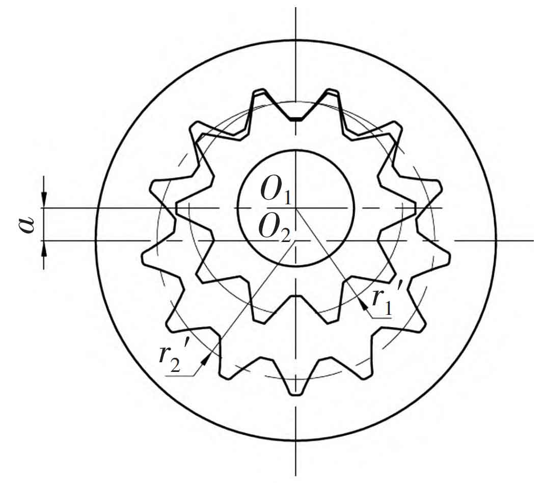
The pitch radius r1 ‘and r2’ of gears can be calculated based on the transmission ratio i and the actual meshing center distance a ‘:
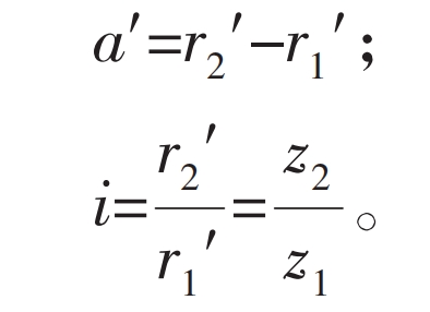
In the formula, z2 is the number of teeth in the internal gear.
For the same linear tooth profile of an external gear, it can conjugate with an internal gear with z2 teeth at different center distances to achieve the same transmission ratio. The corresponding internal gear tooth profile can be calculated using the conjugate principle, but the conjugate tooth profile of the internal gear obtained at different center distances is different, which is different from that of an involute gear pair.
The point where the pressure angle on the inner gear profile is the standard value is also defined as the position of its indexing circle. If the pitch circle of the outer gear of the straight tooth profile coincides with its indexing circle during meshing, the pitch circle of the conjugate inner gear also coincides with its indexing circle because the pressure angle of the pitch circle of the meshing pair is the same. This meshing state is defined as the straight conjugate standard inner meshing, and the two gears must have the same modulus. The meshing center distance is:

The center distance a defined by equation (10) is called the standard center distance. If the center distance is greater than or less than the standard center distance, the inner and outer gears can also mesh, forming a straight conjugate inner mesh with displacement. It should be pointed out again that due to the lack of separability of involute gears, the conjugate curve of the internal gear profile is different for linear conjugate gear pairs meshing at different center distances. Therefore, the study of the displacement problem of linear conjugate internal meshing gear transmission is much more complex.
3. Tooth profile meshing limit point
The tooth profile of the external gear expressed in equation (5) is a straight line that can be wirelessly extended, but in reality, the height of the teeth is limited. When designing, it is necessary to reasonably select a section of this straight line as the tooth profile. The tooth top of the linear external gear tooth profile shown in Figure 5 does not exceed the intersection point A of the tooth profile and the symmetry axis. From the tooth profile equations (5) and (6), it can be concluded that:

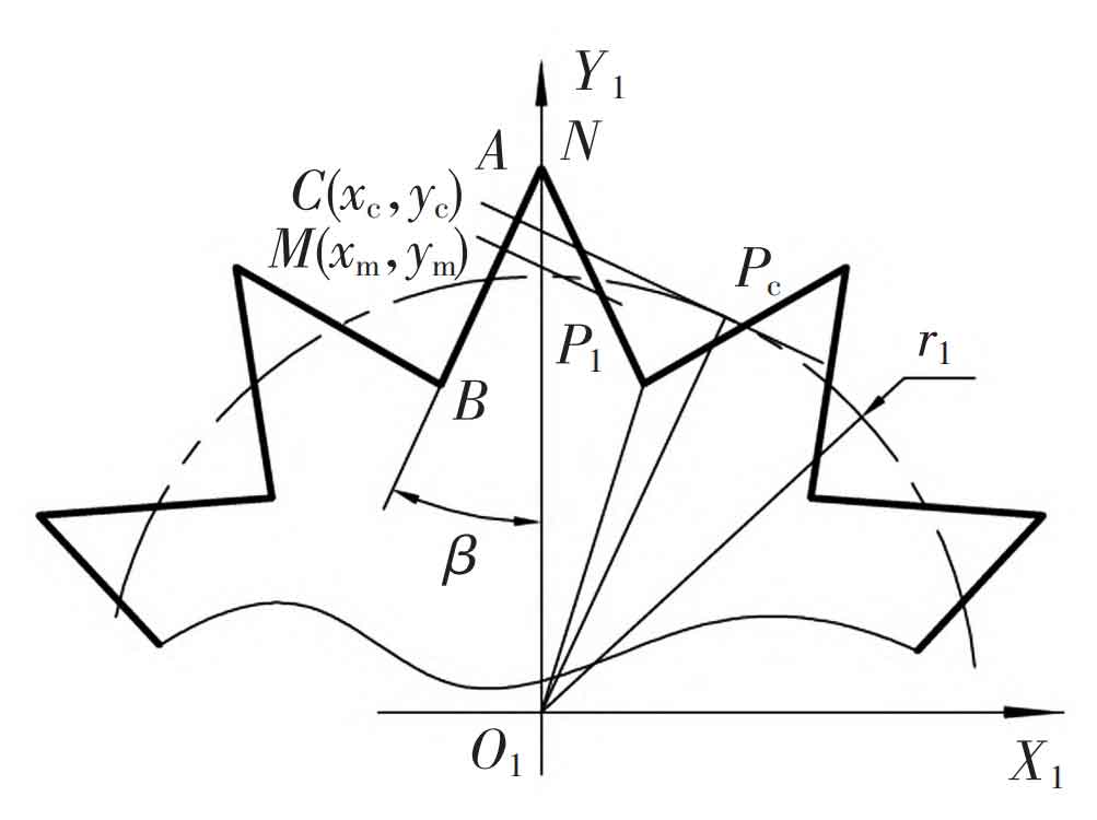
In fact, point A may not necessarily be the limit point when the inner and outer tooth profiles mesh. Draw the normal of the tooth profile at any point M (xm, ym) on the straight tooth profile, and intersect the pitch circle at point P1; Translate point M along with its normal upwards along the tooth profile, and point P1 also moves to the right on the pitch circle, finally reaching the tangent point Pc with the pitch circle. At this point, the corresponding point C (xc, yc) on the tooth profile is the tooth profile meshing limit point. The tooth profile straight line segment that exceeds the meshing limit point does not have a conjugate curve, which may cause tooth profile interference during the meshing process. Therefore, in gear design, the tooth top of the gear cannot exceed point C.
The coordinates of the meshing limit point C can be calculated using the following formula:
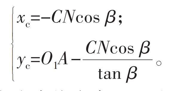
In Figure 4, point N is the intersection point between the normal of the over meshing limit point C on the straight tooth profile and the coordinate axis Y1, where:

Substituting equation (11) into equation (14) yields:

It is obvious that the position of point C is not only determined by the parameters of the straight tooth profile itself, but also by the transmission ratio and center distance of the gear pair. For linear tooth profile external gears with the same modulus and number of teeth, the position of the meshing limit point and the half angle of the tooth top β Regarding, β The larger the value, the higher the position of the limit point. When point C coincides with point A, it can be obtained that:

Following the parameter design method of involute gears, the difference between the radius of the tooth tip circle and the radius of the indexing circle of the straight tooth profile outer gear is the tooth tip height:
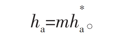
In the formula, h * a is the coefficient of tooth top height.
The meshing limit point C may be located above or below point A. Due to the generally symmetrical tooth profile of the gear teeth, the line segment where point C exceeds point A has no practical significance. Therefore, in gear parameter design, it can be specified that the tooth tip cannot exceed the meshing limit point C.
Due to the convenience of calculating the length CN, the following limiting conditions can be used in gear parameter design:

In the formula, s+a is the thickness of the tooth top chord, which can be calculated by the following formula:

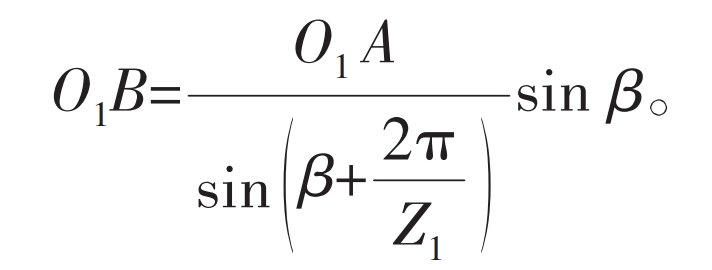
In Figure 4, the straight tooth profile on both sides of the outer gear groove intersects at point B at the tooth root. Obviously, when working on the tooth profile, the meshing point cannot be below point B. Point B is the limit position of the tooth root on the straight tooth profile, and the distance from the center of the outer gear to point B is:
The difference between the radius of the indexing circle and the radius of the tooth root circle of a straight tooth profile external gear is defined as the tooth root height:
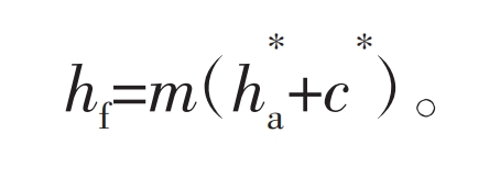
In the formula, c * is the coefficient of top clearance.
4. Mesh line and its characteristics
According to the analysis in the previous section, a straight tooth profile external gear can choose any length between the BC points on the tooth profile line as the tooth profile line of the gear, forming an internal meshing transmission with the conjugate internal gear. However, under actual operating conditions, continuous transmission requirements should also be considered, and the overlap should not be less than 1. A larger overlap can improve the smoothness of the transmission and increase the load-bearing capacity, but in some special situations, such as internal meshing gear pumps, excessive overlap can cause serious oil trapping.
The meshing line is the trajectory of the meshing points in a fixed coordinate frame during the meshing process of a gear pair, which can be solved using the tooth profile normal method. The meshing line can express the meshing characteristics of gear pairs, and can also be used for the calculation of conjugate tooth profiles and the analysis of overlap.
The overlap of gear transmission is mainly related to the height of the teeth, and the relationship between the overlap of involute gears and the tooth height is approximately proportional because their meshing lines are straight. Therefore, when designing the tooth profile, selecting different sections of involute as the tooth profile, there is basically no significant difference in gear height. However, analysis of the meshing process of linear conjugate internal meshing transmission reveals that the relationship between its overlap and tooth height is completely different from that of involute gears.
As shown in Figure 6, the transition point P is the perpendicular line of the outer gear tooth profile g 1, and the perpendicular foot is the meshing point m. Obviously, point m is located on the meshing line.
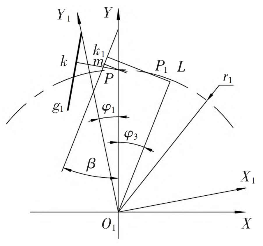
Set point k1 as any point on the tooth profile of the linear external gear, whose coordinates in the coordinate system O1X1Y1 are (x1, y1). The normal of the tooth profile at k1 intersects with the pitch circle of the outer gear at point P1. If k1 is to become the contact point, the outer gear must be rotated counterclockwise relative to the initial position by an angle φ 1. Make point P1 coincide with node P, and at this point, the corresponding position k (x, y) of point k1 in the fixed coordinate system O1XY is the coordinate of the corresponding point on the meshing line.
In Figure 6:

And:
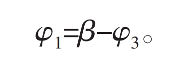
To obtain the coordinates of the corresponding points on the meshing line, the rotation transformation of point k1 is:

The shape of the meshing line of the linear conjugate internal meshing transmission is shown in Figure 7. Starting from the gear tooth root position, the meshing line is relatively straight, but when it approaches the tooth top position of the gear, the degree of curvature of the meshing line increases, which is very different from the involute transmission. In Figure 7 ψ The angle at which the outer gear rotates when a pair of teeth enter and exit meshing. If the radius of the outer gear tooth top circle ra1 is increased, the meshing process between the teeth that should have ended will be greatly extended due to the bending of the meshing line.
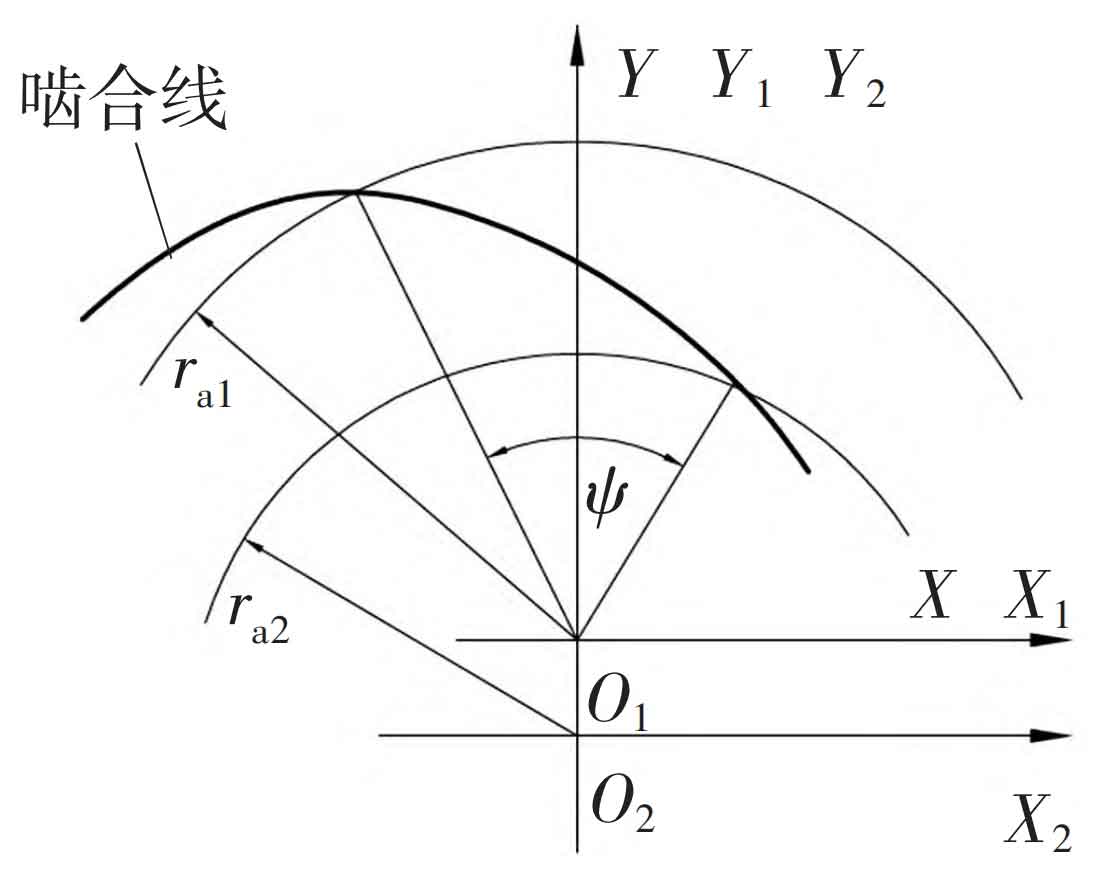
Figure 8 shows the relationship curve between the tooth height of the linear profile external gear and the corresponding meshing angle during the meshing process. The curve starts to deflect upwards near the tooth top position, indicating that the contribution of the tooth height near the tooth top position to the overlap is greater than that of the tooth root part of the tooth profile.
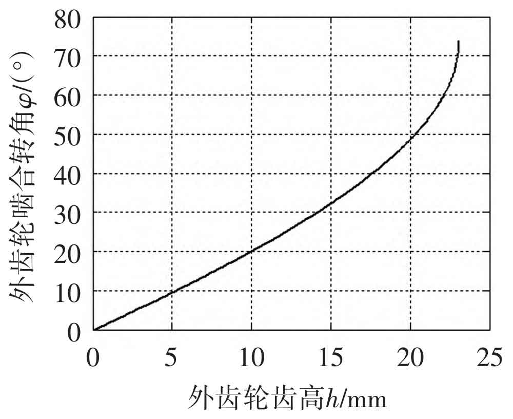
The significance of this characteristic of linear conjugate internal meshing transmission for tooth profile design is that, starting from meeting the requirements of transmission overlap, when the working tooth surface is near the tooth root section of the straight line BC, a larger tooth height is required. The gear pair designed in this way can obtain a relatively large displacement in the internal meshing gear pump and avoid oil trapping phenomenon; If the working tooth surface is in a straight line BC near the tooth top section, a relatively small tooth height can meet the requirements of continuous transmission, so short teeth can be used in planetary transmission to solve the interference problem of internal meshing transmission and improve the bending strength of the gear teeth.
In addition, during the entire meshing process, the speed change of the meshing point on the tooth surface is also relatively large, while the position change of the meshing point is relatively slow when approaching the tooth top. For the internal meshing gear pair in the gear pump, this characteristic can be used to control the position of the meshing point and reduce output flow pulsation. In a word, compared with involute gears, the design of tooth profile parameters of linear conjugate internal meshing transmission has greater flexibility to meet the requirements of different transmission conditions.
5. Coincidence degree
The analysis of the overlap degree of gear transmission requires calculating the angle at which a pair of teeth rotate from entering meshing to exiting meshing. For tooth profile parameter design, the overlap degree mainly depends on the size of the tooth top circle of the outer and inner gears.
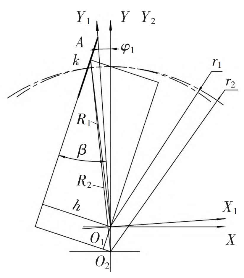
According to the geometric relationship between the straight conjugate internal meshing gear pairs in Figure 9, the distance from the meshing point k to the center O1 of the external gear is:

In the formula: ψ 1 is the angle of the outer gear starting from the initial position, h is the vertical distance from the straight tooth profile to the center of the outer gear, and the calculation formula is:

The distance from the meshing point to the center O2 of the internal gear is:

When the gear pair begins to mesh, there are:
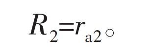
In the formula, ra2 is the radius of the inner gear tooth tip circle.
At the end of meshing, when the tooth tip of the external gear disengages, there are:

By substituting equations (27) and (28) into equations (24) and (26) respectively, the angle of the external gear when a pair of teeth enter and exit meshing can be obtained, and then the overlap degree of the gear transmission can be calculated.
6. Engineering application examples
In order to verify the research results of this article, a pair of involute internal meshing gear pairs used in an internal meshing gear pump were selected, and the gear parameters were redesigned using linear conjugate internal meshing tooth profiles, keeping the center distance and tooth tip radius of the gears the same. The parameter comparison of the two gear pairs is shown in Table . In order to ensure interchangeability, the gear circle, tooth root circle, and center distance of the two pairs of gear pairs are the same. The calculation results show that the main tooth shape parameters of the two types of gear pairs are similar, but there is a significant difference in the pressure angle variation law during the meshing process.
| Gear parameters | Involute gear | Linear conjugate gear |
| Number of outer teeth z1 | 13 | 13 |
| Number of internal teeth z2 | 20 | 20 |
| Module m/mm | 3.50 | 3.42 |
| Dividing circle pressure angle α/ (°) | 25.00 | 29.42 |
| Pressure angle of tooth tip circle α A/(°) | 36.50 | 25.16 |
| Root circle pressure angle α F/(°) | 0 | 33.91 |
| Meshing angle α′/ (°) | 27.35 | 27.66 |
| Meshing overlap ε | 1.382 4 | 1.226 9 |
| Outer gear indexing circle diameter r1/mm | 45.5 | 44.4 |
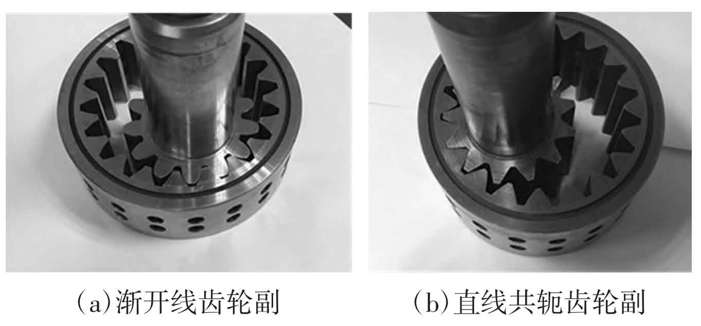
Figure 10 shows a comparison photo of new and old tooth shaped parts. After experimental testing, it was found that the gear pair with linear conjugate teeth worked well in the original involute internal meshing gear pump.
7. Conclusion
1) In linear conjugate internal meshing gear transmission, the pressure angle of the linear tooth profile external gear depends on the half angle of the tooth tip and the number of teeth; The larger the half angle of the tooth tip, the fewer teeth, and the greater the pressure angle; For a given pressure angle, there exists a minimum number of teeth. In addition, the pressure angle decreases with the increase of the meshing point radius, and the minimum pressure angle is equal to the half angle of the tooth tip.
2) There are upper and lower meshing limit points in linear profile external gears, and the meshing limit point at the tooth tip may be smaller than the tooth tip circle, resulting in some tooth profiles not participating in meshing and interference phenomena.
3) A straight tooth profile external gear can form an internal meshing transmission with a conjugate internal gear. The tooth profile curve of the internal gear is related to the center distance, and its meshing line is a curve. The degree of curvature of the meshing line increases near the tooth top position of the gear, and the contribution of the tooth height near the tooth top position to the meshing degree is much greater than that of the tooth root part.
The machining of linear conjugate internal meshing gear pairs is not difficult, and the external gears are similar to triangular external splines, which can be machined on milling machines or hobbing machines and ground using spline grinders; The machining of internal gears adopts broaching technology for large-scale production, which has high production efficiency and easy accuracy assurance. Gear hobbing can also be used for small-scale machining. It can be foreseen that with the deepening of research on the theory of linear conjugate internal meshing transmission, this gear transmission method can not only be better applied in internal meshing gear pumps, but also potentially promoted in fields such as planetary gear transmission.
