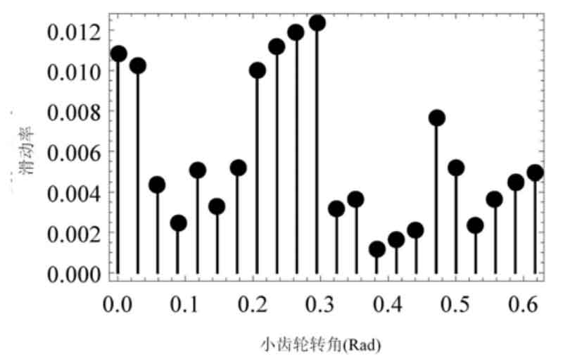
After solving the finite element model, the force distribution of pinion and big gear in power transmission can be obtained. Figure 1 shows the bending and contact stress of the pinion when the contact point is located in the middle of the tooth surface. According to Hertz contact theory, when the two contact surfaces of point contact are in actual contact, the shape of the contact area is ellipse due to the action of elastic deformation. However, because the bending deformation of the tooth root will affect the actual contact situation of the equal angle spiral bevel gear, the contact area is only an approximate ellipse in the finite element analysis results. According to the results of finite element analysis, the changes of single tooth contact stress and bending stress of equiangular spiral bevel gear can be obtained.
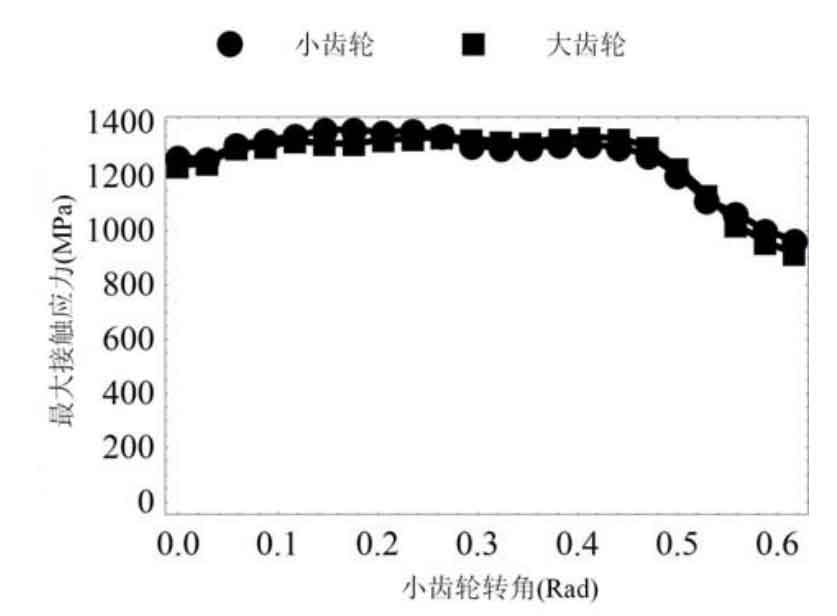
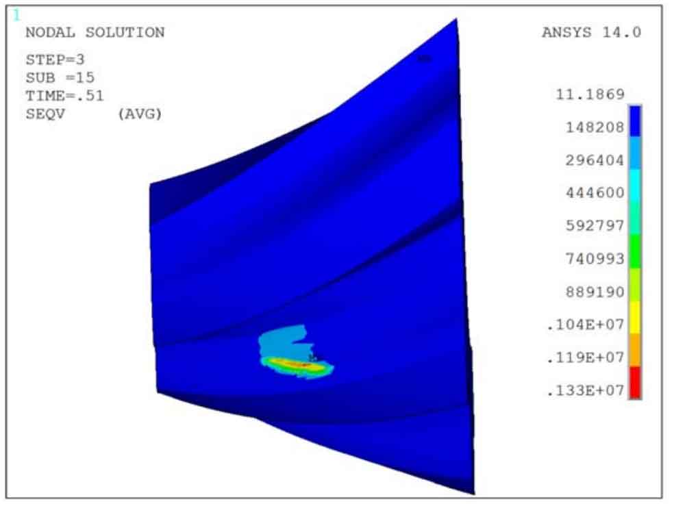
It can be seen from Figure 2 that the maximum contact stress is about 1400MPa in a meshing cycle, while Figure 3 shows the change of the maximum bending stress in a meshing cycle. The maximum bending stress is lower than 250Mpa. The lower maximum bending stress can be mainly attributed to the design of short teeth, large modulus and double circular arc tooth profile.
The point contact area under the geometric assumption of equiangular spiral bevel gear will actually expand into an approximate elliptical surface contact due to the force. For the convenience of analysis, the maximum force point in the finite element analysis of equiangular spiral bevel gear is set as the qualitative contact point, that is, in the actual meshing process, the equiangular spiral bevel gear pair is considered to contact at this point. In the meshing process, the absolute value of the deviation between the actual contact point and the ideal contact point of a single tooth in the wired element analysis is shown in Figure 4.
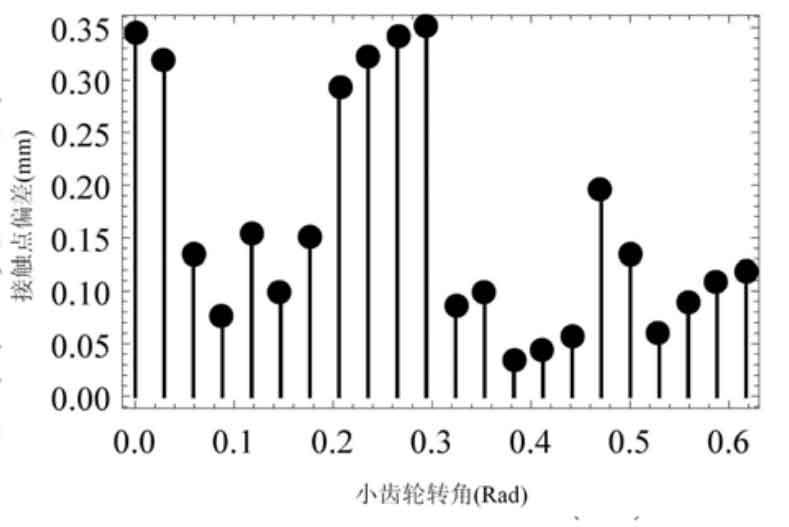
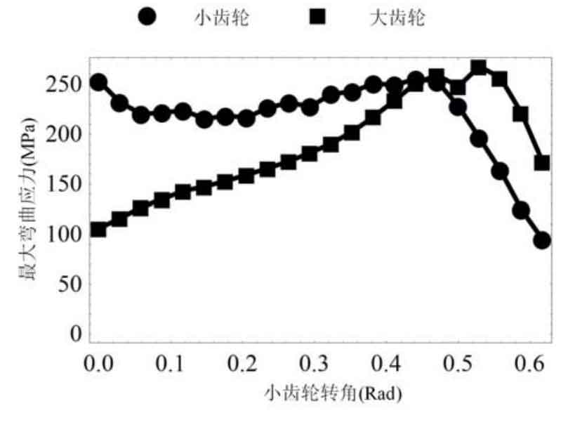
Among them, the maximum qualitative contact point position deviation is 0.35mm, which is small. Therefore, it can be considered that the actual contact point position is consistent with the theoretical contact point position. In the qualitative contact point, since its position is not on the theoretical contact line, generally speaking, there is no 0 sliding rate, that is, pure rolling meshing property. After calculation, in the actual finite element analysis, the actual sliding rate of equiangular helix conjugate curve bevel gear pair should be as shown in Figure 5. It can be seen that the sliding rate is still maintained at a low level (maximum 0.012).