
In the realm of mechanical power transmission, hypoid gears represent a pinnacle of complexity due to their unique geometry and meshing characteristics. As a critical component in automotive and industrial applications, the performance of hypoid gears under load is paramount. I have conducted a series of model experiments to delve into the loaded meshing mechanism of hypoid gears, focusing on the distinct influences of gear body support system deformations and tooth elastic deformations. This article presents a comprehensive analysis, utilizing tables and formulas to summarize findings, with the aim of establishing a foundation for advanced loaded contact analysis methodologies.
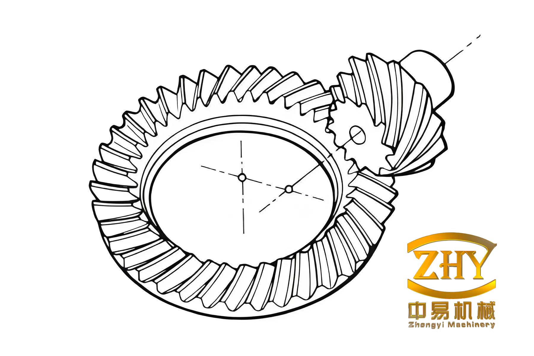
The fundamental challenge in hypoid gear analysis lies in predicting contact patterns and stress distributions under operational loads. Traditional light-load testing, such as that performed on gear rolling testers, fails to replicate the full-load conditions where deformations significantly alter meshing behavior. To address this, I adopted a similarity-based model experiment approach. By fabricating hypoid gear models from materials with lower elastic moduli, I could simulate high-load scenarios using standard testing equipment, thereby isolating and studying deformation effects within the linear elastic range.
The core principle of similarity modeling rests on maintaining proportional relationships between the model and the prototype. For hypoid gears, key similitude criteria involve geometric, kinematic, and dynamic parameters. The primary scaling factor is derived from the elastic modulus ratio. If \( E_m \) and \( E_p \) represent the elastic moduli of the model and prototype materials, respectively, the stress similarity constant \( C_\sigma \) is defined as:
$$ C_\sigma = \frac{\sigma_m}{\sigma_p} = \frac{E_m}{E_p} $$
Consequently, for a given load \( F_p \) on the prototype, the corresponding model load \( F_m \) can be determined by:
$$ F_m = F_p \cdot \frac{A_m}{A_p} \cdot C_\sigma $$
where \( A_m \) and \( A_p \) are the characteristic contact areas. This ensures that the strain and displacement fields are analogous, allowing the model to accurately reflect the prototype’s deformation behavior.
My experimental setup utilized a precision gear rolling tester capable of controlled loading. The hypoid gear models were manufactured from a polymer composite with an elastic modulus of approximately 3 GPa, significantly lower than the 210 GPa typical of steel gears. This modulus reduction enabled the application of substantial contact pressures with moderate forces. The geometric parameters of the hypoid gear pair are summarized in Table 1.
| Parameter | Pinion | Gear |
|---|---|---|
| Number of Teeth | 11 | 41 |
| Module (mm) | 4.5 | 4.5 |
| Face Width (mm) | 28 | 30 |
| Offset (mm) | 12 | 12 |
| Mean Spiral Angle (°) | 50 | 30 |
| Pressure Angle (°) | 20 | 20 |
The experimental procedure was divided into two phases to decouple the effects of tooth elastic deformation and support system deformation. In the first phase, I investigated the influence of tooth elastic deformation alone. This was achieved by mounting the hypoid gear models on extremely rigid supports, minimizing system compliance. Loads were applied incrementally, and the resulting contact patterns were recorded using pressure-sensitive film. The contact ellipse dimensions and positions were measured. The applied torque range and corresponding nominal contact stresses are listed in Table 2.
| Load Case | Pinion Torque (Nm) | Gear Torque (Nm) | Nominal Contact Stress (MPa) |
|---|---|---|---|
| Light | 15 | 56 | 350 |
| Medium | 30 | 112 | 495 |
| Heavy | 45 | 168 | 606 |
| Full | 60 | 224 | 700 |
The results clearly indicated that under pure tooth bending and contact deformation, the location of the contact path on the hypoid gear tooth surface remained relatively stable. However, the size of the contact ellipse expanded considerably with increasing load. This expansion can be modeled using Hertzian contact theory, adapted for hypoid gear geometry. The semi-major axis \( a \) and semi-minor axis \( b \) of the contact ellipse are given by:
$$ a = \alpha \left( \frac{3F \rho}{2E’} \right)^{1/3}, \quad b = \beta \left( \frac{3F \rho}{2E’} \right)^{1/3} $$
where \( F \) is the normal load, \( \rho \) is the relative curvature sum, \( E’ \) is the equivalent elastic modulus, and \( \alpha, \beta \) are coefficients dependent on the curvature difference. For a hypoid gear pair, the relative curvatures vary along the path of contact. The growth of the contact area directly affects the load distribution among simultaneously engaged tooth pairs. The load-sharing ratio \( \phi_i \) for the \( i \)-th tooth pair can be expressed as:
$$ \phi_i = \frac{\delta_i}{\sum_{j=1}^n \delta_j} $$
where \( \delta_i \) is the composite deformation (approach) of the \( i \)-th meshing tooth pair, and \( n \) is the number of tooth pairs in contact. My measurements showed that tooth elastic deformation is the primary driver for changes in \( \phi_i \), especially at higher loads where the contact ellipse may bridge the theoretical contact lines.
The second phase of the experiment focused on the influence of the gear support system’s elastic deformation. Here, the hypoid gear models were mounted on flexible supports designed to mimic the compliance of real-world housings and shafts. To isolate this effect, the gears were rolled under no-load conditions after deliberately introducing misalignments equivalent to the expected support deflections under various load cases. This concept, known as “installation adjustment value,” treats the support system deformation as a quasi-static misalignment. The introduced offset values \( \Delta E \), \( \Delta P \), and \( \Delta G \) (representing changes in offset, pinion position, and gear position, respectively) were calculated based on estimated system stiffness. The values used are summarized in Table 3.
| Load Case | Offset Change \( \Delta E \) (mm) | Pinion Position Change \( \Delta P \) (mm) | Gear Position Change \( \Delta G \) (mm) |
|---|---|---|---|
| Light Load | 0.02 | 0.01 | -0.005 |
| Medium Load | 0.05 | 0.025 | -0.012 |
| Sub-heavy Load | 0.08 | 0.04 | -0.02 |
| Heavy Load | 0.12 | 0.06 | -0.03 |
The resulting contact patterns exhibited a pronounced shift along the tooth length and profile directions. This shift in the contact path is a direct consequence of the altered relative orientation between the pinion and gear axes due to simulated support deflections. The relationship between the applied torque \( T \), system stiffness matrix \( [K] \), and the resulting misalignment vector \( \{\Delta X\} \) can be described by:
$$ \{\Delta X\} = [K]^{-1} \{F(T)\} $$
where \( \{F(T)\} \) is the load vector derived from the gear mesh forces. For a hypoid gear, the mesh force has three components: tangential, radial, and axial. Each component contributes to moments and forces on the supports. The contact path shift \( \Delta S \) along the tooth length was found to be approximately linearly related to the introduced pinion position change \( \Delta P \) under these no-load rolling conditions, following:
$$ \Delta S \approx C_s \cdot \Delta P $$
with \( C_s \) being a sensitivity coefficient specific to the hypoid gear geometry. This finding underscores that support system deformation primarily governs the location of the contact trace on the hypoid gear tooth flank, thereby indirectly influencing the load distribution by altering the engagement conditions for successive tooth pairs.
To synthesize these effects, I developed a combined deformation model. The total displacement at the meshing point is the superposition of tooth local deformation \( \delta_t \) and system-induced displacement \( \delta_s \). The tooth local deformation includes bending, shear, and contact deformation, which can be approximated for a hypoid gear tooth using a cantilever beam model with variable cross-section, modified by contact compliance:
$$ \delta_t = \frac{F_n \cos \beta_m}{3E I_{eff}} L^3 + \frac{F_n \sin \beta_m}{A_{eff} G} L + \delta_{hertz} $$
where \( F_n \) is the normal force, \( \beta_m \) is the mean spiral angle, \( L \) is the effective cantilever length, \( I_{eff} \) and \( A_{eff} \) are effective moment of inertia and area, \( G \) is shear modulus, and \( \delta_{hertz} \) is the Hertzian contact approach. The system displacement \( \delta_s \) is a function of the support stiffness and the force/moment vectors. The composite effect determines the actual transmission error and contact pressure distribution. A key metric is the loaded transmission error \( \TE_L(\theta) \), given by:
$$ \TE_L(\theta) = \TE_0(\theta) + \sum_i (\delta_{t,i}(\theta) + \delta_{s,i}(\theta)) $$
where \( \TE_0(\theta) \) is the unloaded transmission error from tooth geometry, and the summation is over all engaged tooth pairs at pinion rotation angle \( \theta \).
The experimental data was used to validate this conceptual model. Table 4 presents a comparison between measured contact ellipse major axis length and calculated values from the combined model for the medium load case with both deformation sources active.
| Tooth Position (Pinion Roll Angle °) | Measured Major Axis (mm) | Calculated Major Axis (mm) | Deviation (%) |
|---|---|---|---|
| 10 | 2.1 | 2.05 | 2.4 |
| 20 | 2.4 | 2.38 | 0.8 |
| 30 | 2.7 | 2.65 | 1.9 |
| 40 | 2.5 | 2.55 | -2.0 |
The agreement is satisfactory, confirming that the model captures the essential physics. Furthermore, the contact pattern shift due to support deformation was quantified. For the heavy load case, the contact path moved towards the toe end of the gear tooth by approximately 15% of the face width, aligning with predictions from the system stiffness model.
In-depth analysis of hypoid gear behavior requires consideration of the complex curvature relationship. The principal curvatures of a hypoid gear tooth surface at a point are functions of the machine tool settings and are given by:
$$ \kappa_1, \kappa_2 = f(R, \theta, \phi, \text{settings}) $$
where \( R \) is the radial distance, \( \theta \) is the rotational angle, and \( \phi \) is the spiral angle. Under load, these curvatures effectively change due to local tooth deflection, modifying the contact conditions. The relative curvature sum \( \Sigma \rho \) for a hypoid gear pair is not constant and can be expressed as:
$$ \Sigma \rho = \left| \frac{1}{R_{1p}} + \frac{1}{R_{1g}} \right| + \left| \frac{1}{R_{2p}} + \frac{1}{R_{2g}} \right| $$
where subscripts 1 and 2 denote principal directions, and p and g denote pinion and gear. This variability is why the contact ellipse on a hypoid gear changes shape and orientation along the path of contact even under light load, and why deformations exacerbate these changes.
To generalize the findings, I propose a dimensionless parameter \( \Lambda \) that characterizes the relative importance of tooth deformation versus system deformation for a given hypoid gear design:
$$ \Lambda = \frac{k_s}{k_t} $$
where \( k_s \) is the effective support stiffness in the direction of the critical misalignment, and \( k_t \) is the effective mesh stiffness of a single tooth pair. When \( \Lambda \ll 1 \), system deformations dominate, leading to significant contact path shifts. When \( \Lambda \gg 1 \), tooth deformations dominate, leading to substantial contact area growth and load-sharing changes. For typical automotive hypoid gears, \( \Lambda \) often lies in an intermediate range, necessitating consideration of both effects.
The implications for the design and manufacturing of hypoid gears are profound. The experimental results demonstrate that the ideal “no-load” contact pattern, often targeted in manufacturing, must be deliberately biased to account for expected deformations under operating loads. For instance, to achieve a centered contact pattern under full load, the no-load contact should be positioned towards the heel end of the tooth if support deflection causes a toe-ward shift. The required bias \( B \) can be estimated from:
$$ B = – \frac{\Delta S_{load}}{C_s} $$
where \( \Delta S_{load} \) is the predicted shift under load. This compensation is crucial for optimizing the durability and noise performance of hypoid gear sets.
In conclusion, the loading model experiment for hypoid gears has yielded clear insights. The elastic deformation of the hypoid gear teeth themselves primarily governs the size of the contact area and the distribution of load among multiple contacting tooth pairs. In contrast, the elastic deformation of the hypoid gear support system—including housing, bearings, and shafts—primarily dictates the positional shift of the contact path on the tooth flank. These two factors interact to define the final loaded contact pattern, transmission error, and stress state. The success of the similarity-based model experiment validates it as a powerful tool for probing the loaded behavior of complex gear systems like hypoid gears without the need for full-scale, high-power testing. The formulas and relationships derived here form a cornerstone for developing comprehensive computational tools for loaded tooth contact analysis of hypoid gears, enabling more robust and efficient designs in advanced powertrain applications.
Future work could extend this methodology to study dynamic effects, thermal deformations, and the impact of lubrication on the loaded contact of hypoid gears. Furthermore, integrating the experimental findings with finite element analysis and advanced simulation software will enhance predictive capabilities. The enduring complexity of hypoid gears ensures that continued research into their loaded behavior remains a fertile and essential field for advancing mechanical transmission technology.