
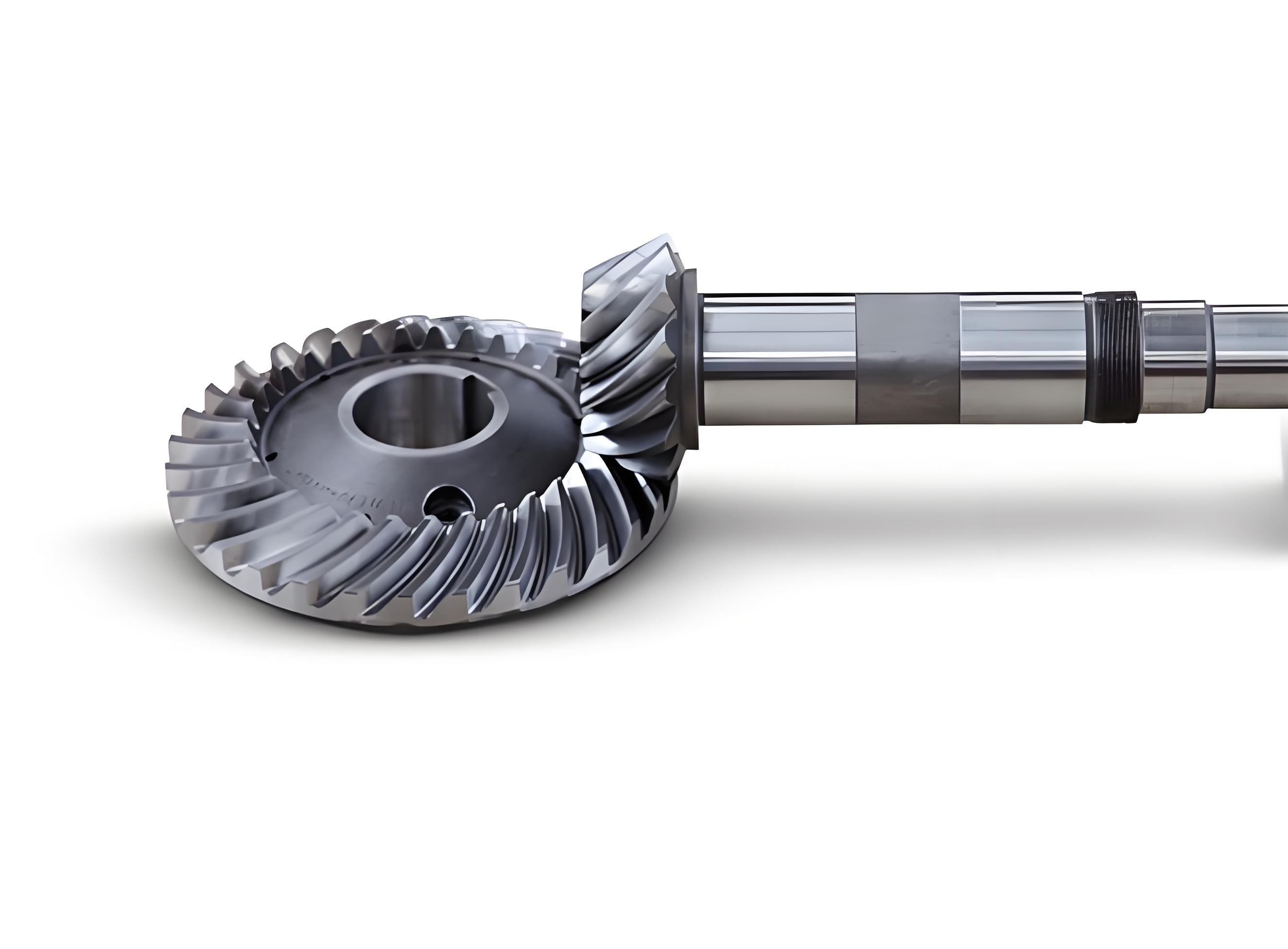
In my study I focus on the design, modeling, and mechanical evaluation of a logarithmic spiral bevel gear pair. A spiral bevel gear is a critical component in mechanical transmission systems because it can carry high loads, operate with high efficiency, run smoothly, and tolerate high speed. These qualities make the spiral bevel gear widely useful in automotive drive axles, construction machinery, energy equipment, aerospace mechanisms, and rolling mill drives. However, when a spiral bevel gear runs at high speed, it may experience impact and vibration, and when the required load capacity increases, the contact length along the tooth surface becomes a limiting factor. For this reason, the logarithmic spiral bevel gear has been proposed as an advanced form of spiral bevel gear that can provide smoother motion transmission and greater load capacity, especially in high-speed and heavy-load transmission systems. In my work I use SolidWorks together with C language programming to build a parametric numerical table for a logarithmic spiral bevel gear. I then use a dimension-driven parametric method to create a three-dimensional model of a pair of logarithmic spiral bevel gears. I verify the structural rationality of the chosen gear parameters through meshing assembly and motion analysis. I also use the SolidWorks Simulation module for mesh generation and nonlinear finite element analysis of the solid mesh. The main purpose of my analysis is to investigate the maximum contact stress, contact strength, and contact strain at the meshing region of the spiral bevel gear under different torque loads. These results allow me to ensure that the designed logarithmic spiral bevel gear has sufficient strength and reliability. After checking, I find that the contact strength of the logarithmic spiral bevel gear remains safe when the applied torque is below a certain optimal value, and the maximum meshing stress is smaller than the yield limit of the material. The results provide a reliable reference and method for the structural design and transmission strength of a logarithmic spiral bevel gear, and they are useful for engineering practice and gear design in related fields.
The material I selected for the logarithmic spiral bevel gear is a P91 chromium-molybdenum alloy heat-resistant steel forging. Its main chemical composition includes carbon, silicon, manganese, chromium, and molybdenum. This alloy has high high-temperature strength, good creep resistance, oxidation resistance, and corrosion resistance. Compared with carbon steel, the P91 alloy offers higher strength and toughness. The material properties I used in the finite element analysis are listed in the following table.
| Material property | Value | Unit |
|---|---|---|
| Elastic modulus | 210000 | N/mm² |
| Poisson ratio | 0.28 | Dimensionless |
| Shear modulus | 79000 | N/mm² |
| Mass density | 7700 | kg/m³ |
| Tensile strength | 723.825 | MPa |
| Yield strength | 620.422 | MPa |
| Thermal expansion coefficient | 0.0000013 | 1/K |
For the geometric design of the logarithmic spiral bevel gear, I use SolidWorks as a secondary development platform and combine it with C language programming. I establish a program that can automatically complete a parametric model of a logarithmic spiral bevel gear. The modeling method is dimension-driven and parametric, which means that when I change basic parameters such as module, number of teeth, and pressure angle, I can quickly create a new spiral bevel gear. The parameter table used for parametric modeling is summarized below. In the table, the phrase “interface input” means that the value is entered through the program interface according to the design requirement.
| Parameter name | Symbol | Input type or formula |
|---|---|---|
| Number of teeth | \(z\) | Interface input |
| Large end module | \(m\) | Interface input |
| Face width | \(b\) | Interface input |
| Addendum height coefficient | \(h_a^*\) | Interface input |
| Clearance coefficient | \(c^*\) | Interface input |
| Working tooth height | \(h’\) | \(h’ = m(2h_a^* + c^*)\) |
| Shaft angle | \(\Sigma\) | \(90^\circ\) |
| Spiral angle | \(\beta\) | Interface input |
| Pitch diameter | \(d_1\) | \(d_1 = \frac{mz}{\cos\delta}\) |
| Pitch cone angle | \(\delta\) | \(\delta = \arctan\left(\frac{z_1}{z_2}\right)\) |
| Outer diameter | \(d_e\) | \(d_e = d + 2h_a\cos\delta\) |
| Crown distance | \(X_e\) | \(X_e = R_e\cos\delta – h_a\sin\delta\) |
| Addendum | \(h_a\) | \(h_a = mh_a^*\) |
| Full tooth height | \(h\) | \(h = m(2h_a^* + c^*)\) |
| Dedendum | \(h_f\) | \(h_f = m(1.25 + \cot\beta)\) |
| Tip cone angle | \(\delta_a\) | \(\delta_a = \delta + \theta_a\) |
| Root cone angle | \(\delta_f\) | \(\delta_f = \delta – \theta_f\) |
| Addendum circle diameter | \(d_a\) | \(d_a = d + 2h_a\cos\delta\) |
| Dedendum circle diameter | \(d_f\) | \(d_f = (d – 2h_f\cos\delta)\cos\delta\) |
| Pressure angle | \(\alpha\) | \(\alpha = \arctan\left(\frac{\tan\beta}{\cos\gamma}\right)\) |
Using the input interface of the parametric program, I can conveniently set the parameters needed for the logarithmic spiral bevel gear model. This parameterized modeling method greatly improves modeling efficiency and accuracy and provides convenience for gear design and analysis. I input the numbers of teeth \(z_1 = 18\) and \(z_2 = 36\) for the small gear and the large gear into the formulas shown above. The resulting geometric parameter values for the spiral bevel gear pair are given in the following table.
| Name | Symbol | Small gear | Large gear |
|---|---|---|---|
| Number of teeth | \(z\) | 18 | 36 |
| Large end module (mm) | \(m_t\) | 2.5 | 2.5 |
| Face width (mm) | \(b\) | 12.7 | 12.7 |
| Addendum height coefficient | \(h_a^*\) | 1 | 1 |
| Clearance coefficient | \(c^*\) | 0.25 | 0.25 |
| Working tooth height (mm) | \(h’\) | 4.38 | 4.38 |
| Shaft angle (°) | \(\Sigma\) | 90 | 90 |
| Spiral angle (°) | \(\beta\) | 35 | 35 |
| Spiral direction | — | Right-hand | Left-hand |
| Pitch diameter (mm) | \(d\) | 45 | 90 |
| Pitch cone angle (°) | \(\delta\) | 26.5651 | 63.3 |
| Crown distance (mm) | \(R\) | 6.38 | 6.35 |
| Mounting distance (mm) | \(p\) | 50.77206 | 50.27422 |
| Addendum (mm) | \(h_a\) | 2.90322 | 2.54 |
| Full tooth height (mm) | \(h\) | 4.79552 | 5.60832 |
| Dedendum (mm) | \(h_f\) | 1.89484 | 3.01752 |
| Tip cone angle (°) | \(\delta_a\) | 30.3475 | 50.3324 |
| Root cone angle (°) | \(\delta_t\) | 24.4435 | 42.328 |
For the contact stress of the spiral bevel gear, I use the gear transmission design formulas. The tooth surface contact stress is expressed as
$$
\sigma_H = Z_E \sqrt{ K_A K_V K_{H\beta} Z_R \frac{300 T_{\max}}{b d_1^2 I} \frac{T_1}{T_{1\max}} }
$$
and the contact strength safety factor is expressed as
$$
S_H = \frac{\sigma_{H\lim} Z_{NT} Z_W}{\sigma_H Z_\theta}
$$
In these equations, \(\sigma_H\) is the tooth surface contact stress, \(T_1\) is the pinion working torque, \(b\) is the face width, \(d_1\) is the large end pitch diameter of the pinion, \(Z_E\) is the elastic coefficient, \(K_A\) is the application factor, \(K_V\) is the dynamic factor, \(K_{H\beta}\) is the load distribution factor, \(Z_R\) is the surface condition factor, \(I\) is the geometric coefficient for tooth surface contact strength, \(S_H\) is the contact strength safety factor, \(\sigma_{H\lim}\) is the contact fatigue limit, \(Z_{NT}\) is the contact fatigue strength life factor, \(Z_W\) is the work hardening factor, and \(Z_\theta\) is the temperature factor. The values of the logarithmic spiral bevel gear contact stress parameters are listed in the following table.
| Parameter meaning | Parameter value | Parameter meaning | Parameter value |
|---|---|---|---|
| Elastic coefficient \(Z_E\) | 189.8 | Stress cycle factor \(Z_{NT}\) | 1.97 |
| Overload factor \(K_A\) | 1.0 | Hardness ratio factor \(Z_W\) | 1.0 |
| Dynamic factor \(K_V\) | 1.0 | Geometric coefficient \(I\) | 1.23 |
| Contact load distribution \(K_{H\beta}\) | 1.8 | Size factor \(Z_X\) | 4.1 |
| Temperature factor \(Z_\theta\) | 0.85 | Surface condition factor \(Z_R\) | 0.85 |
I select a minimum safety factor of 1.25. Under this condition the gear will not fail and remains in a safe state. I also assume that the input power of the pinion is \(P\) and the rotational speed is \(n\). The relationship between torque and power is
$$
T = \frac{9549 P}{n}
$$
Based on the dimension-driven parametric modeling method and the numerical values listed above, I use SolidWorks software to build the digital model of the logarithmic spiral bevel gear. To evaluate its strength and rationality, I check the strength using the theoretical contact stress formulas and perform meshing fit and motion analysis for the small gear and the large gear. This verifies the structural rationality of the designed spiral bevel gear. The resulting logarithmic spiral bevel gear assembly provides the basis for the finite element analysis.
In the SolidWorks Simulation module, the fineness of the mesh affects both the simulation calculation speed and the accuracy of the analysis results. When I perform overall mesh generation for the logarithmic spiral bevel gear, I use a relatively large mesh size, and I apply a finer mesh in the gear meshing region to improve the mesh accuracy and the accuracy of the analysis results. The mesh type I use is a solid mesh, the mesh quality is set to high, and the mesh element size is set to 1.5 mm. In total I generate 158106 elements and 234797 nodes. This mesh arrangement allows the spiral bevel gear contact region to be resolved more accurately while keeping the overall model computationally manageable.
In the static stress analysis, I preserve the rotational degree of freedom of the driving pinion about its axis, constrain its other degrees of freedom, and apply a torque load. The driven large gear is fully constrained. I apply torques of 50, 100, 150, and 200 N·m to the driving pinion and set the friction coefficient to 0.1 for the stress analysis. The stress analysis results show that when the torques of 50, 100, 150, and 200 N·m are applied to the gear pair, the corresponding maximum stresses are 469.6, 644.2, 1227, and 4704 MPa. The maximum stress is mainly concentrated in the gear meshing region, the tooth root, and the tooth tip. These regions are more likely to deform and fail. The local probe results for the meshing region are summarized in the following table.
| Applied torque on pinion (N·m) | Maximum stress (MPa) | Minimum stress (MPa) | Average stress (MPa) |
|---|---|---|---|
| 50 | 420.20 | 0.1769 | 38.98 |
| 100 | 644.20 | 0.2503 | 70.73 |
| 150 | 1227.00 | 0.3677 | 104.10 |
| 200 | 4704.00 | 0.4542 | 138.50 |
According to the stress analysis results, when a torque of 50 N·m is applied to the pinion, the maximum stress at the gear meshing region is 420.20 MPa, which is smaller than the yield strength of 620.422 MPa listed for the material. When a torque of 100 N·m is applied, the maximum stress at the gear meshing region is 644.20 MPa, which slightly exceeds the yield limit of 620.422 MPa, so the gear experiences slight deformation. However, when torques of 150 and 200 N·m are applied, the maximum stresses at the gear meshing region reach 1227 and 4704 MPa, respectively, which are far beyond the yield limit and cause severe deformation of the spiral bevel gear.
Therefore, I need to refine the torque range between 50 and 100 N·m to find the best value at which the maximum stress in the meshing region of the spiral bevel gear does not exceed the yield strength of the material, so that no permanent deformation or fracture occurs within the load-carrying range. In the static stress analysis, I apply torques of 60, 60.5, 61, and 65 N·m to the small driving gear and set the friction coefficient to 0.1. The resulting stress analysis data are given in the following table.
| Applied torque on pinion (N·m) | Maximum stress (MPa) | Minimum stress (MPa) | Average stress (MPa) |
|---|---|---|---|
| 60 | 456.90 | 0.2033 | 43.75 |
| 60.5 | 447.00 | 0.2095 | 44.78 |
| 61 | 2640.00 | 0.1388 | 43.40 |
| 65 | 736.20 | 0.2172 | 48.98 |
The logarithmic spiral bevel gear has relatively large axial force and radial force, which makes the force distribution more complex. When the torque is between 60 and 65 N·m, the force conditions at the tooth tip, tooth root, and meshing region of the spiral bevel gear may change, causing stress concentration in a local region and leading to a local maximum stress. When the torque is 100 N·m, the force condition changes, and the local stress is dispersed to other locations, so the location and magnitude of the local maximum stress change. This explains why the local maximum stress at 60 to 65 N·m can be higher than the local maximum stress at 100 N·m in the probe results. Comparing the results, when I apply torques of 60 and 60.5 N·m to the pinion, the maximum stresses in the meshing region are 456.9 and 447.0 MPa, respectively, both of which are smaller than the material yield limit of 620.422 MPa. However, when I apply torques of 61 and 65 N·m, the maximum stresses in the meshing region reach 2640 and 736.2 MPa, which exceed the material yield limit and cause severe deformation and failure of the spiral bevel gear. Therefore, to ensure that the logarithmic spiral bevel gear meshes normally and reliably, the applied torque should not exceed 60.5 N·m.
For the contact strength check, I apply a torque of 60.5 N·m to the pinion. I substitute \(T_1 = 60.5\ \text{N·m}\) and \(T_{1\max} \approx T_1\) into the contact stress formula. The allowable contact stress of the gear tooth surface is 484 MPa. According to the probe results, in the working state the maximum contact stress of the gear tooth surface is 447 MPa, which does not exceed the allowable contact stress. Therefore, when the torque applied to the pinion does not exceed 60.5 N·m, the spiral bevel gear remains within the allowable stress range and meets the strength requirement. This result is important for the structural design of the logarithmic spiral bevel gear because it defines a practical torque limit for safe operation.
In the static stress analysis, I apply torques of 50, 100, 150, and 200 N·m to the pinion and set the friction coefficient to 0.1 for displacement analysis. The displacement results for the gear meshing region are summarized in the following table.
| Applied torque (N·m) | Maximum displacement (mm) | Minimum displacement (mm) |
|---|---|---|
| 50 | 0.2075 | \(1\times10^{-30}\) |
| 100 | 0.1815 | \(1\times10^{-30}\) |
| 150 | 0.1624 | \(1\times10^{-30}\) |
| 200 | 0.1384 | \(1\times10^{-30}\) |
From the displacement results, I observe several effects. First, the maximum displacement in the sampled region changes as the torque increases, but the change is not a simple linear increase. In the analyzed range, the maximum nodal displacement decreases from 0.2075 mm at 50 N·m to 0.1384 mm at 200 N·m. This behavior indicates that the location of maximum displacement shifts and that the contact pattern redistributes the deformation within the gear pair. The minimum displacement remains effectively zero, which is consistent with the constrained regions of the model. Second, the spiral bevel gear tooth tip is more likely to deform when torque is applied to the pinion. Third, once the torque becomes high enough for the deformation to reach the material limit, the maximum displacement will increase sharply until the spiral bevel gear fails. Therefore, the displacement data should be interpreted together with the stress data and the contact strength check rather than as an independent safety criterion.
My overall findings can be summarized as follows. I selected P91 chromium-molybdenum alloy forged steel for the logarithmic spiral bevel gear. I used the SolidWorks secondary development platform and C language programming to build a parametric table for the logarithmic spiral bevel gear. By entering the corresponding parameters, I automatically created the spiral bevel gear model. Based on the dimension-driven parametric modeling method, I quickly created a three-dimensional model of a pair of logarithmic spiral bevel gears with 18 and 36 teeth. I performed meshing assembly and motion simulation to verify the rationality of the gear structure. I then used the SolidWorks Simulation module to analyze the stress and strain at the meshing region of the spiral bevel gear. The results show that the torque applied to the driving gear should not exceed 60.5 N·m. At this torque, the maximum stress at the gear meshing region is 456.9 MPa, which is smaller than the material yield strength of 620.422 MPa, so the logarithmic spiral bevel gear does not undergo plastic deformation. Through the theoretical gear contact stress formula, I checked the gear contact strength. The result shows that within the allowable stress range, the contact strength requirement is satisfied. I further analyzed the strain of the gear meshing region and found that within a certain range the maximum displacement of the logarithmic spiral bevel gear changes with torque, and the tooth tip of the meshing gear is more prone to deformation.
The design and analysis procedure I used can be expressed in a compact parametric form. The pitch cone angle is determined by the tooth numbers:
$$
\delta_1 = \arctan\left(\frac{z_1}{z_2}\right), \qquad \delta_2 = \arctan\left(\frac{z_2}{z_1}\right)
$$
The pitch diameter relation for the spiral bevel gear is
$$
d = \frac{mz}{\cos\delta}
$$
The addendum and dedendum relations are
$$
h_a = mh_a^*, \qquad h_f = m(1.25 + \cot\beta)
$$
The full tooth height is
$$
h = m(2h_a^* + c^*)
$$
The tip cone angle and root cone angle are
$$
\delta_a = \delta + \theta_a, \qquad \delta_f = \delta – \theta_f
$$
The pressure angle is
$$
\alpha = \arctan\left(\frac{\tan\beta}{\cos\gamma}\right)
$$
For contact stress evaluation, the governing relation is
$$
\sigma_H = Z_E \sqrt{ K_A K_V K_{H\beta} Z_R \frac{300 T_{\max}}{b d_1^2 I} \frac{T_1}{T_{1\max}} }
$$
and the contact safety factor is
$$
S_H = \frac{\sigma_{H\lim} Z_{NT} Z_W}{\sigma_H Z_\theta}
$$
For power and torque conversion I used
$$
T = \frac{9549 P}{n}
$$
These equations allowed me to connect the geometric parameters of the logarithmic spiral bevel gear with the load capacity and contact strength. Because the spiral bevel gear is sensitive to load distribution, the finite element model must include the meshing region with sufficient mesh density. In my model, the solid mesh with 158106 elements and 234797 nodes provided a reasonable balance between accuracy and computational cost.
The contact stress and displacement results also show the importance of load range selection for the spiral bevel gear. When the applied torque is too low, the gear pair may not reach its optimal contact pattern, and when the applied torque is too high, the contact stress can exceed the material yield limit. In my analysis, the transition occurs near 60.5 N·m. At 60 N·m and 60.5 N·m, the maximum stresses are 456.9 MPa and 447.0 MPa, both below the yield strength. At 61 N·m and 65 N·m, the maximum stresses rise to 2640 MPa and 736.2 MPa, which are above the yield strength. This sharp change is caused by stress concentration and by the complex axial and radial force components in the spiral bevel gear. The local contact region can become critically loaded even when the nominal torque increase is small. Therefore, the safe torque range should be defined conservatively, and the spiral bevel gear should be designed with enough margin against contact fatigue and plastic deformation.
The contact strength check further supports the torque limit. At 60.5 N·m, the allowable contact stress is 484 MPa, and the maximum contact stress is 447 MPa. The maximum contact stress is lower than the allowable contact stress, so the contact strength requirement is satisfied. The maximum stress is also lower than the material yield strength of 620.422 MPa. This means that the logarithmic spiral bevel gear can operate safely at or below 60.5 N·m under the assumed friction coefficient and boundary conditions. If the torque is increased beyond this value, the contact stress and von Mises stress may exceed the material limits, and the spiral bevel gear may experience plastic deformation, pitting, or other contact fatigue damage.
The displacement results add another perspective. The maximum displacement values at 50, 100, 150, and 200 N·m are 0.2075, 0.1815, 0.1624, and 0.1384 mm, respectively. The minimum displacement remains essentially zero. This trend shows that the maximum displacement in the sampled region does not simply grow with torque. Instead, the deformation pattern changes as the load increases. The tooth tip of the spiral bevel gear is more prone to deformation, which suggests that the tip region should be carefully controlled during manufacturing and assembly. In a practical design, tooth tip relief, contact pattern adjustment, and proper backlash selection can help reduce the risk of tip interference and local deformation. For the logarithmic spiral bevel gear, the spiral angle and the logarithmic tooth trace influence the contact path, so the designer should consider both the global load distribution and the local geometry at the tooth tip and root.
From a design standpoint, the parametric model I created provides a fast way to evaluate different spiral bevel gear configurations. The dimension-driven method allows the number of teeth, module, face width, addendum coefficient, clearance coefficient, shaft angle, and spiral angle to be changed without rebuilding the entire model manually. The C language program and the numerical parameter table make the process repeatable. When the parameters are changed, the formulas listed above update the pitch diameter, pitch cone angle, outer diameter, crown distance, addendum, full tooth height, dedendum, tip cone angle, root cone angle, addendum circle diameter, dedendum circle diameter, and pressure angle. This is especially useful for the logarithmic spiral bevel gear because its tooth surface geometry is more complex than that of a straight bevel gear or a conventional spiral bevel gear. The parametric approach reduces the risk of geometric errors and improves the consistency between the theoretical design and the three-dimensional model.
The finite element analysis workflow I used can also be summarized in a table.
| Analysis step | Setting or result |
|---|---|
| Software platform | SolidWorks with Simulation module |
| Model type | Solid mesh of a logarithmic spiral bevel gear pair |
| Mesh quality | High |
| Element size | 1.5 mm |
| Number of elements | 158106 |
| Number of nodes | 234797 |
| Driving gear boundary | Rotational degree of freedom about its axis retained; other degrees constrained |
| Driven gear boundary | Fully constrained |
| Friction coefficient | 0.1 |
| Applied torques for coarse study | 50, 100, 150, 200 N·m |
| Applied torques for refined study | 60, 60.5, 61, 65 N·m |
| Critical safe torque | 60.5 N·m |
| Maximum contact stress at safe torque | 447 MPa |
| Allowable contact stress | 484 MPa |
| Yield strength | 620.422 MPa |
I also compare the stress results in a compact table to show the margin against yield strength.
| Torque (N·m) | Maximum stress (MPa) | Yield strength (MPa) | Status |
|---|---|---|---|
| 50 | 420.20 | 620.422 | Safe |
| 60 | 456.90 | 620.422 | Safe |
| 60.5 | 447.00 | 620.422 | Safe |
| 61 | 2640.00 | 620.422 | Unsafe |
| 65 | 736.20 | 620.422 | Unsafe |
| 100 | 644.20 | 620.422 | Slightly unsafe |
| 150 | 1227.00 | 620.422 | Unsafe |
| 200 | 4704.00 | 620.422 | Unsafe |
The contact strength check can also be expressed as a ratio:
$$
\frac{\sigma_H}{\sigma_{H\allow}} = \frac{447}{484} \approx 0.924
$$
This ratio is smaller than 1, so the contact strength is acceptable at 60.5 N·m. The stress ratio with respect to yield strength is
$$
\frac{\sigma_{\max}}{\sigma_y} = \frac{447}{620.422} \approx 0.720
$$
This ratio is also smaller than 1, which means the logarithmic spiral bevel gear remains in the elastic range at the recommended torque. For comparison, at 61 N·m the stress ratio is
$$
\frac{2640}{620.422} \approx 4.26
$$
which is far above 1 and indicates severe plastic deformation risk. At 65 N·m the ratio is
$$
\frac{736.2}{620.422} \approx 1.19
$$
which also exceeds 1. These simple ratios help explain why the safe torque limit should be set at 60.5 N·m rather than at a higher value.
For the displacement analysis, I can define a normalized displacement change relative to the 50 N·m case:
$$
\Delta_{\max}(T) = \frac{u_{\max}(T) – u_{\max}(50)}{u_{\max}(50)}
$$
Using the tabulated values, the maximum displacement at 100 N·m is about 12.5% lower than at 50 N·m, at 150 N·m it is about 21.7% lower, and at 200 N·m it is about 33.3% lower. This normalized view shows that the deformation pattern changes significantly with load. However, this trend should not be interpreted as unlimited improvement in safety. The stress results show that beyond 60.5 N·m the local stress can exceed the yield limit, so the displacement trend is only valid while the gear remains within the elastic contact regime and the load distribution remains stable.
The logarithmic spiral bevel gear therefore requires a combined evaluation of contact stress, contact strength, and displacement. A single criterion is not enough. The contact stress tells me whether the tooth surface may fail by pitting or fatigue. The safety factor tells me whether the contact strength has enough margin. The displacement tells me where the gear pair may deform and how the contact pattern may shift. The finite element analysis of the spiral bevel gear should include these three aspects. In my study, the maximum stress is concentrated at the meshing region, tooth root, and tooth tip. The tooth tip is especially prone to deformation. The contact stress at 60.5 N·m remains below the allowable contact stress. The maximum stress remains below the yield strength. Therefore, the logarithmic spiral bevel gear design is safe and reliable for torques up to 60.5 N·m under the assumed conditions.
I can also summarize the parametric design formulas in a single reference table for the spiral bevel gear.
| Design quantity | Formula |
|---|---|
| Pitch cone angle | \(\delta = \arctan\left(\frac{z_1}{z_2}\right)\) |
| Pitch diameter | \(d = \frac{mz}{\cos\delta}\) |
| Working tooth height | \(h’ = m(2h_a^* + c^*)\) |
| Addendum | \(h_a = mh_a^*\) |
| Dedendum | \(h_f = m(1.25 + \cot\beta)\) |
| Full tooth height | \(h = m(2h_a^* + c^*)\) |
| Outer diameter | \(d_e = d + 2h_a\cos\delta\) |
| Crown distance | \(X_e = R_e\cos\delta – h_a\sin\delta\) |
| Tip cone angle | \(\delta_a = \delta + \theta_a\) |
| Root cone angle | \(\delta_f = \delta – \theta_f\) |
| Addendum circle diameter | \(d_a = d + 2h_a\cos\delta\) |
| Dedendum circle diameter | \(d_f = (d – 2h_f\cos\delta)\cos\delta\) |
| Pressure angle | \(\alpha = \arctan\left(\frac{\tan\beta}{\cos\gamma}\right)\) |
| Torque from power | \(T = \frac{9549 P}{n}\) |
| Contact stress | \(\sigma_H = Z_E \sqrt{ K_A K_V K_{H\beta} Z_R \frac{300 T_{\max}}{b d_1^2 I} \frac{T_1}{T_{1\max}} }\) |
| Contact safety factor | \(S_H = \frac{\sigma_{H\lim} Z_{NT} Z_W}{\sigma_H Z_\theta}\) |
The numerical results of the spiral bevel gear study can be summarized in a final comparison table.
| Quantity | Value or range |
|---|---|
| Pinion tooth number | 18 |
| Large gear tooth number | 36 |
| Large end module | 2.5 mm |
| Face width | 12.7 mm |
| Spiral angle | 35° |
| Shaft angle | 90° |
| Material | P91 chromium-molybdenum alloy steel forging |
| Elastic modulus | 210000 N/mm² |
| Poisson ratio | 0.28 |
| Density | 7700 kg/m³ |
| Yield strength | 620.422 MPa |
| Tensile strength | 723.825 MPa |
| Meshing element size | 1.5 mm |
| Number of elements | 158106 |
| Number of nodes | 234797 |
| Friction coefficient | 0.1 |
| Safe torque limit | 60.5 N·m |
| Maximum stress at safe torque | 447 MPa |
| Allowable contact stress | 484 MPa |
| Maximum displacement at 50 N·m | 0.2075 mm |
| Maximum displacement at 200 N·m | 0.1384 mm |
| Most deformation-prone region | Tooth tip of the meshing spiral bevel gear |
In conclusion, my work demonstrates a complete parametric design and mechanical analysis process for a logarithmic spiral bevel gear. I use SolidWorks and C language programming to build the parameter table and create the three-dimensional model. I verify the structure through meshing assembly and motion analysis. I use nonlinear finite element analysis to study the contact stress, contact strength, and contact strain under different torques. The results show that the applied torque on the driving gear should not exceed 60.5 N·m. At this torque, the maximum stress at the meshing region is 456.9 MPa, which is smaller than the material yield strength of 620.422 MPa, so the logarithmic spiral bevel gear does not undergo plastic deformation. The theoretical contact stress check also shows that the contact strength is within the allowable range. The displacement analysis shows that the tooth tip of the meshing spiral bevel gear is more prone to deformation, and the maximum displacement pattern changes with torque. These findings provide a reliable reference and method for the structural design and transmission strength of a logarithmic spiral bevel gear. They are useful for engineering practice and gear design in related fields, especially where a spiral bevel gear must operate under high speed, high load, and high reliability requirements.