
Abstract
In the field of mechanical transmission, gear transmission is widely used in various manufacturing industries due to its advantages of small center distance and high transmission ratio. However, dry milling of contour bevel gears generates high cutting forces and temperatures, leading to poor machined surface quality, low machining efficiency, and uneven distribution of the metamorphic layer due to plastic deformation of the workpiece material. Therefore, it is of great significance to study the machined surface quality and metamorphic layer of contour bevel gears. This paper conducted research on the machined surface quality and metamorphic layer of contour bevel gears through finite element simulation and experimental investigation.
1. Introduction
This section introduces the research background and significance, the current research status of contour bevel gear machining technology and machined surface quality at home and abroad, as well as the research content and sources of the topic.
2. Principle of Contour Bevel Gear Milling and Simulation Analysis of Residual Height
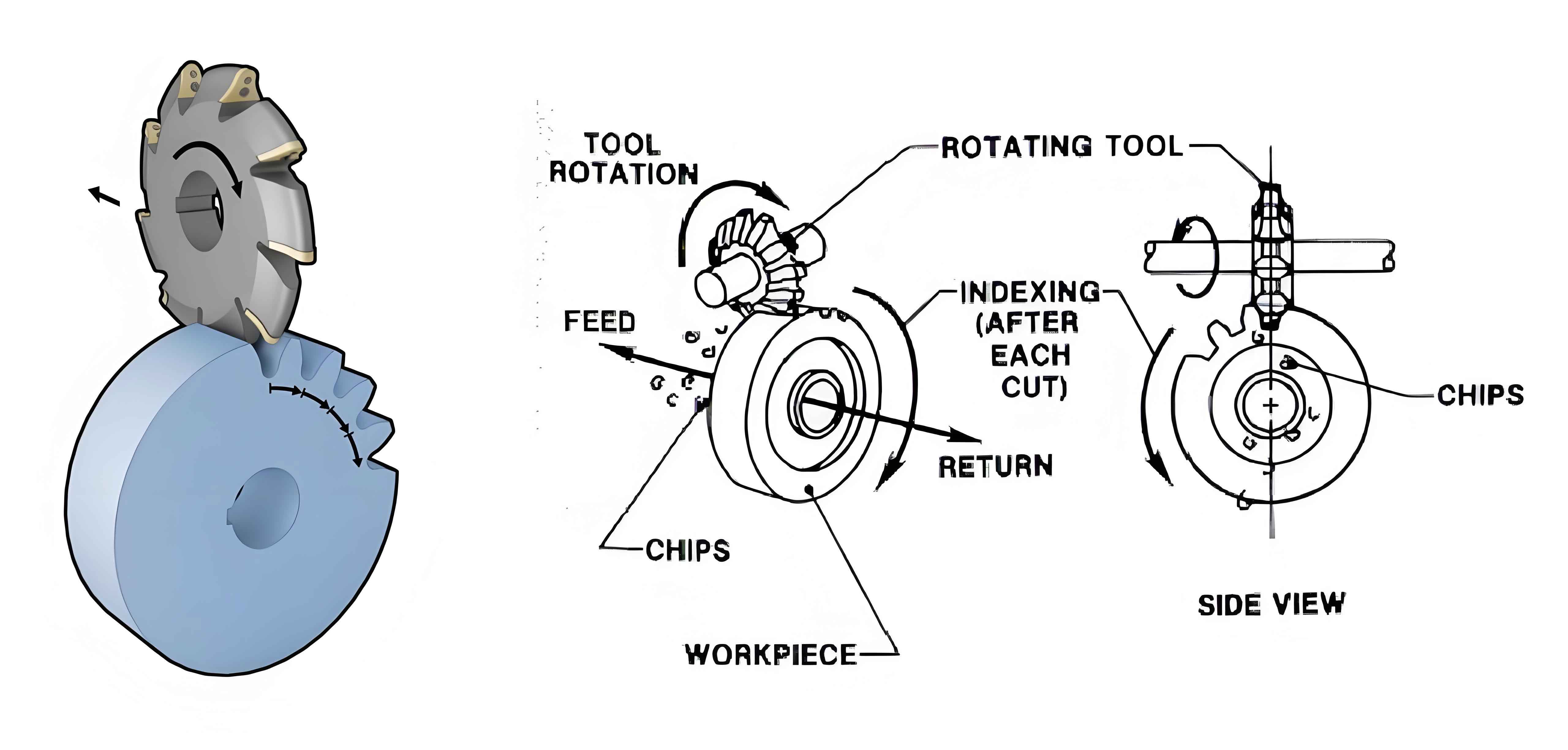
2.1 Meshing Principle of Contour Bevel Gears
This section discusses the gear meshing theory and local conjugate conditions, establishing a milling coordinate system based on the meshing theory and the generating method of bevel gear milling.
2.2 Residual Height Formation Mechanism
Based on the gear cutting surface model and tool cutting mathematical model, the formation mechanism of the average residual height on the tooth surface is explored.
2.3 Simulation Analysis
Simulation analysis is conducted to investigate the influence of cutting parameters on the residual height on the tooth surface, establishing a method to characterize the roughness of contour bevel gear tooth surfaces.
Table 1: Simulation Parameters
| Parameter | Value |
|---|---|
| Cutting speed (v) | Various values |
| Feed rate (f) | Various values |
| Tool material | Carbide |
| Workpiece material | Alloy steel |
2.4 Simulation Results
The simulation results show that as the cutting speed increases, the average residual height on the tooth surface decreases, while it increases with the feed rate.
3. Finite Element Simulation of Cutting Process
The cutting tool and gear blank are simplified reasonably, and the DEFORM simulation software is used for assembly, mesh generation, boundary condition definition, and solution calculation. The main cutting force and the temperature field, strain field, and strain rate of the metamorphic layer at different depths from the machined surface are extracted and analyzed to investigate the influence of cutting parameters.
Table 2: FE Simulation Parameters
| Parameter | Value |
|---|---|
| Simulation software | DEFORM |
| Element type | Tetrahedral |
| Boundary conditions | Fixed and moving |
| Cutting force extraction | Yes |
| Temperature field analysis | Yes |
4. Experimental Investigation of Machined Surface Quality
Dry milling experiments are conducted on contour bevel gears to analyze the influence of cutting speed and feed rate per tooth on the surface roughness and surface morphology of the machined surface.
4.1 Experimental Conditions and Materials
The experimental conditions, materials, and preparation of metallographic samples for the machined surface are described.
Table 3: Experimental Conditions
| Parameter | Value |
|---|---|
| Cutting speed (v) | 170-260 m/min |
| Feed rate per tooth (f) | 0.1-0.3 mm/r |
| Tool material | Carbide |
| Workpiece material | Alloy steel |
4.2 Experimental Results
4.2.1 Error Analysis
The error analysis of the machined tooth surface of contour bevel gears is presented.
4.2.2 Surface Roughness Analysis
The surface roughness analysis is conducted using a white light interferometer.
Table 4: Surface Roughness Measurement Data (f = 0.1 mm/r)
| Cutting speed (v) | Sa (μm) | Sq (μm) | Ra (μm) |
|---|---|---|---|
| 170 m/min | … | … | … |
| 200 m/min | … | … | … |
| 230 m/min | … | … | … |
| 260 m/min | … | … | … |
4.2.3 Surface Morphology Analysis
The surface morphology analysis is conducted using scanning electron microscopy (SEM).
4.3 Surface Defect Research
SEM and energy-dispersive spectroscopy (EDS) are used to study and analyze the surface defects of the machined surface.
4.4 XRD Diffraction Analysis
X-ray diffraction (XRD) is used to compare the diffraction peaks of the microcrystalline grains of the machined surface and the substrate material, and the influence of cutting parameters on the hardness of the machined surface is investigated through hardening tests.
4.5 Work Hardening Analysis
The work hardening analysis of the tooth surface is presented.
5. Research on Metamorphic Layer and Work Hardening in Contour Bevel Gear Milling
5.1 Preparation of Metallographic Samples
The preparation of metallographic samples for the machined metamorphic layer is described.
5.2 XRD Diffraction Analysis of the Machined Surface Metamorphic Layer
XRD is used to characterize the metamorphic layer, exploring the laws of grain refinement and material phase transformation.
5.3 Metallographic Microscopic Morphology Observation
The metallographic microscopic morphology is observed using an ultra-depth microscope.
5.4 Influence of Cutting Parameters on Metamorphic Layer Thickness
The influence of cutting parameters on the thickness of the machined surface metamorphic layer is studied using SEM and EDS.
Conclusion
Contour bevel gears, as an important branch of spiral bevel gears, have the advantages of low noise and good stability. Therefore, the machining process of contour bevel gears has been extensively studied by many scholars. However, the quality of the tooth surface has a significant impact on the transmission accuracy of the gears. Meanwhile, during the machining process, the workpiece material is prone to plastic deformation, resulting in uneven distribution of the metamorphic layer. Therefore, it is necessary to study the machined surface quality and metamorphic layer characteristics of contour bevel gears to provide theoretical and technical support for the maturity and improvement of the cutting process of contour bevel gears.
Based on the principle of contour bevel gear milling, this paper studied the machined surface quality and metamorphic layer of contour bevel gears through finite element simulation and experimental investigation of the cutting process. The following conclusions were drawn:
- The meshing principle of contour bevel gears and the milling process were discussed, and an analytical relationship between the residual height on the tooth surface and the cutting parameters was established. Simulation analysis revealed that the residual height decreases with increasing cutting speed and increases with increasing feed rate. A method to estimate the roughness of spiral bevel gear tooth surfaces was proposed.
- Finite element simulation of the single-tooth cutting process of contour bevel gears was conducted. The main cutting force and the temperature field, strain field, and strain rate of the metamorphic layer at different depths from the machined surface were analyzed. The cutting parameters were optimized, with the final optimized results being a cutting speed of 257.63 m/min and a feed rate of 0.12 mm/r, providing parameter optimization for contour bevel gear milling experiments.
This research provides a theoretical basis and technical support for improving the machining accuracy and transmission efficiency of contour bevel gears, as well as optimizing their surface quality.