
I have investigated the machining of fillet surfaces on a spiral bevel gear because the fillet region at the tooth tip and tooth end controls several important functional characteristics of the final transmission. In my work, I treat the spiral bevel gear not merely as a gear with a complex tooth surface, but as a complete manufacturing problem in which geometry, tool accessibility, tool axis orientation, surface finish, and dimensional consistency must be solved together. The spiral bevel gear is widely used in aviation, aerospace, marine, automotive, and high-load power transmission systems because it has a large contact ratio, high load capacity, smooth operation, and relatively low noise. However, the fillet surface on the spiral bevel gear is difficult to produce by conventional manual methods. Manual grinding often produces local variation, visible transition marks, uneven edge quality, and inconsistent radius values. I therefore developed a digital manufacturing route in which a five-axis CNC machining center, UG CAM programming, CLS tool location data, dedicated post-processing, and VERICUT simulation are combined to machine the fillet surface of the spiral bevel gear with controlled accuracy and repeatability.
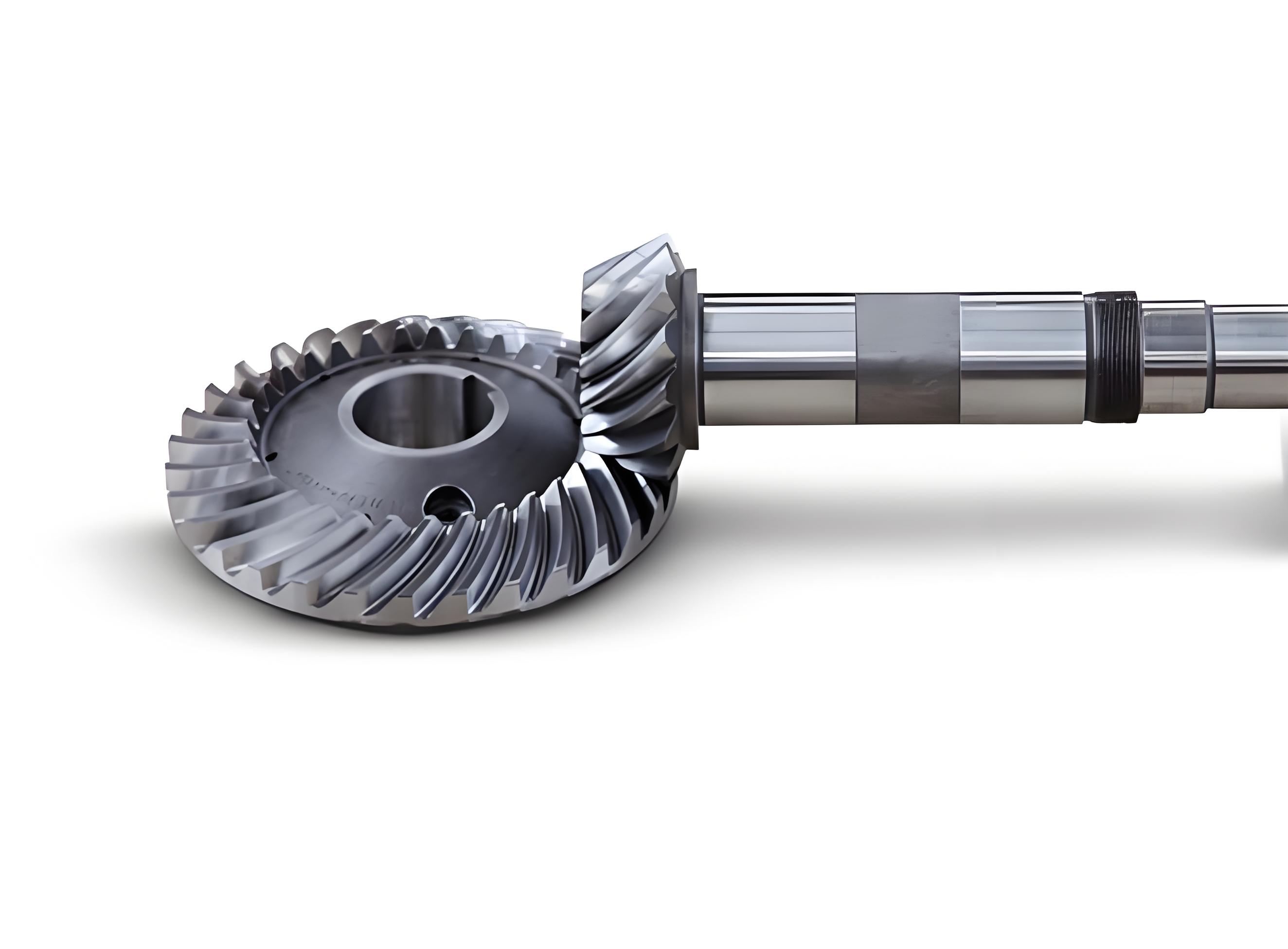
My central objective is to improve and guarantee the surface quality of the fillet on the spiral bevel gear while increasing machining efficiency. I replace the previous reliance on manual polishing with a numerically controlled five-axis machining method. I use the CAM function of UG software to perform automatic programming of the spiral bevel gear surface, and I use its simulated machining function to check whether the tool path is correct. I also perform surface precision inspection and verify that the simulation process has no interference and no collision. The generated CLS tool location file is processed by a dedicated post-processor to obtain an NC program. Finally, I use VERICUT software as a virtual five-axis machining center platform to simulate the machining of the fillet surface on the spiral bevel gear. Through this route, the tooth profile fillet of the spiral bevel gear reaches 0.3 mm with a tolerance of plus or minus 0.07 mm, the surface roughness value reaches 0.64 micrometers, and the overall consistency is good enough to satisfy the design requirements. My conclusion is that a traditional five-axis linked machine tool can be used to chamfer and round the tooth profile of a spiral bevel gear, and that an ideal tooth profile fillet size and improved surface precision can be obtained.
In my manufacturing philosophy, the spiral bevel gear fillet surface is not a secondary detail. It is a functional surface that reduces stress concentration, improves shifting or meshing smoothness, lowers noise and impact, and extends service life. When the fillet on the spiral bevel gear is poorly formed, the tooth tip may retain a sharp edge, the contact pattern may become irregular, and the tooth root or tooth tip may experience localized loading. When the fillet on the spiral bevel gear is formed accurately, the transition from the tooth flank to the tooth tip becomes smooth, the edge quality becomes stable, and the entire gear set can operate with less vibration. Therefore, I define the fillet surface of the spiral bevel gear as a precision feature rather than a deburring operation.
Before I describe the machining route, I summarize the main variables I use. The following table gives my working notation for the spiral bevel gear fillet problem.
| Symbol | Meaning in my spiral bevel gear study | Typical unit |
|---|---|---|
| R_f | Nominal fillet radius on the spiral bevel gear | mm |
| Delta_R | Allowed fillet radius deviation | mm |
| R_a | Arithmetic mean surface roughness | micrometer |
| D_t | Cutting tool diameter | mm |
| r_t | Tool corner radius or ball radius | mm |
| s | Stepover or side step | mm |
| v_c | Cutting speed | m/min |
| f_z | Feed per tooth | mm/tooth |
| n | Spindle speed | r/min |
| a_p | Axial depth of cut | mm |
| a_e | Radial width of cut | mm |
| u, v | Parametric coordinates on the spiral bevel gear surface | dimensionless |
| P(u,v) | Point on the spiral bevel gear tooth surface | mm |
| T | Tool axis vector | dimensionless |
| e_i | Dimensional error at inspection point i | mm |
I use a parametric representation for the spiral bevel gear surface so that the tool path can be planned in a systematic way. I describe a point on the tooth surface as a vector function:
$$ \mathbf{P}(u,v) = \begin{bmatrix} x(u,v) \\ y(u,v) \\ z(u,v) \end{bmatrix} $$
For the fillet surface on the spiral bevel gear, I extend the same parametric idea to a blended surface between the tooth flank and the tooth tip or tooth end. I represent the fillet as a transition surface:
$$ \mathbf{F}(u,v) = \mathbf{P}_1(u) + R_f \mathbf{N}_1(u) \cos v + R_f \mathbf{B}_1(u) \sin v $$
Here P_1 is the boundary curve on the tooth flank, N_1 is the surface normal at that boundary, and B_1 is a tangent direction along the edge. In my practical CAM work, I do not need to solve this equation explicitly for every point because UG constructs the blend surface from the CAD model. However, the equation helps me understand why the tool axis orientation must be controlled carefully. If the tool axis is not aligned well with the local normal or with the local blend direction, the effective radius of the cutting tool changes, and the actual fillet on the spiral bevel gear deviates from the nominal value.
The relationship between the nominal tool radius and the actual fillet radius is central to my method. For a ball-end tool, the theoretical fillet radius produced by the tool is related to the tool geometry and the contact condition. I use the following simple relationship as a first approximation:
$$ R_f \approx r_t – \frac{s^2}{8 r_t} $$
This expression shows that increasing the stepover s tends to reduce the effective fillet quality and can also change the apparent radius. In my process, I keep the stepover small for the fillet operations. For the top fillet on the spiral bevel gear, I use s = 0.2 mm. For the outer fillet on the spiral bevel gear, I also use s = 0.2 mm. This small stepover is one reason that the final surface roughness reaches 0.64 micrometers.
I also use the standard scallop height relationship to estimate the surface quality left by the finishing pass on the spiral bevel gear:
$$ h \approx \frac{s^2}{8R} $$
Here h is the scallop height and R is the effective cutter radius. If I need a specific surface roughness on the spiral bevel gear fillet, I can rearrange this equation to choose an upper bound for the stepover:
$$ s \leq \sqrt{8 R h_{max}} $$
For my finishing operations, I combine this geometric estimate with the practical cutting parameters of the five-axis machine. The result is a tool path in which the stepover is small enough to produce a smooth fillet on the spiral bevel gear without making the machining time excessive.
I now describe the design requirements that I imposed on the spiral bevel gear. The gear I studied requires a tooth tip surface roughness of R_a = 0.8 micrometers, a tooth tip and tooth end fillet of R = 0.3 mm, and a dimensional accuracy of plus or minus 0.1 mm. These requirements are strict because the fillet on the spiral bevel gear is small relative to the tooth size, and the tool must approach the tooth tip without colliding with the adjacent tooth. The following table summarizes my design target and the final simulated result.
| Requirement | Design target for the spiral bevel gear | Result from my simulation | Status |
|---|---|---|---|
| Tooth tip surface roughness | R_a = 0.8 micrometers | R_a = 0.64 micrometers | Pass |
| Tooth tip fillet radius | R = 0.3 mm | R = 0.3 plus or minus 0.07 mm | Pass |
| Tooth end fillet radius | R = 0.3 mm | R = 0.3 plus or minus 0.07 mm | Pass |
| Dimensional accuracy | Plus or minus 0.1 mm | Residual values between -0.005195 mm and 0.01167 mm | Pass |
| Interference and collision | No interference, no collision | No interference, no collision detected | Pass |
Because the spiral bevel gear has a complex tooth geometry, I do not attempt to machine the entire fillet in a single operation. I divide the process into several operations. Each operation has a specific cutting region, tool type, tool diameter, corner radius, stepover, and cutting speed. This decomposition is essential for controlling tool access and for avoiding interference on the spiral bevel gear. The following table lists the main process parameters that I use in my CAM setup.
| Cutting region on the spiral bevel gear | Tool diameter (mm) | Tool type | Corner radius (mm) | Stepover (mm) | Cutting speed (m/min) |
|---|---|---|---|---|---|
| Overall contour | 20 | Ring cutter | 4 | 2 | 60 |
| Tooth tip surface | 10 | Ball-end cutter | 5 | 1 | 70 |
| Gear top fillet | 6 | Ball-end cutter | 3 | 0.2 | 70 |
| Tooth outer fillet | 4 | Ball-end cutter | 2 | 0.2 | 70 |
| Tooth profile concave and convex surfaces | 4 | Ball-end cutter | 2 | 0.2 | 70 |
I choose a ring cutter for the overall contour because it is efficient for removing material around the spiral bevel gear tooth spaces. I choose ball-end cutters for the tooth tip surface, the gear top fillet, the tooth outer fillet, and the tooth profile surfaces because they can approach the curved surfaces of the spiral bevel gear smoothly and can produce a continuous blend. The reduction in tool diameter from 20 mm to 10 mm to 6 mm to 4 mm follows the natural order of the spiral bevel gear geometry: larger tools remove bulk material, and smaller tools create the fine fillet surface.
My complete process route for the spiral bevel gear is as follows. I first perform rough and semi-finish machining of the overall contour. I then finish the tooth tip surface. I then finish the gear top fillet. I then finish the tooth outer fillet. Finally, I finish the tooth profile concave and convex surfaces. I keep the same general strategy throughout: I use the CAD model of the spiral bevel gear as the master geometry, and I let UG CAM generate the tool path from that model. The following table gives my operation sequence in a compact form.
| Operation number | Operation name for the spiral bevel gear | CAM method | Axis mode | Cutting pattern |
|---|---|---|---|---|
| 1 | Overall contour rough and semi-finish | Cavity milling | Five-axis machine with three-axis linkage | Follow part, depth first |
| 2 | Tooth tip surface finish | Fixed-axis contour milling | Five-axis machine with three-axis linkage | Reciprocating, surface drive |
| 3 | Gear top fillet finish | Variable-axis contour milling | Five-axis five-linkage | Reciprocating, surface drive |
| 4 | Tooth outer fillet finish | Fixed-axis and variable-axis contour milling | Five-axis three-linkage and five-linkage | Reciprocating, surface drive |
| 5 | Tooth profile concave and convex finish | Fixed-axis contour milling and cavity milling | Five-axis three-linkage | Reciprocating and layer first |
For operation 1, I use cavity milling with a depth-first cutting order. The cutting region includes all tooth features of the spiral bevel gear except the bottom plane. I leave 0.5 mm of stock for the subsequent finishing operations. The cutting pattern follows the part, which means the tool tends to follow the local shape of the spiral bevel gear rather than a simple parallel path. This is useful because the spiral bevel gear tooth spaces are curved and non-uniform.
For operation 2, I use fixed-axis contour milling for the tooth tip surface of the spiral bevel gear. I choose a reciprocating cutting pattern and a surface drive method. The projection vector points toward the drive body. This operation removes the remaining stock on the tooth tip and creates a smooth base for the fillet.
For operation 3, I use variable-axis contour milling for the gear top fillet of the spiral bevel gear. The nominal fillet radius is 0.3 mm. The cutting region includes the two curved fillet zones at the top of the spiral bevel gear tooth. The tool axis changes during the cut because the local surface normal changes along the fillet. This is where the five-axis capability becomes essential. If I used only three-axis machining, the tool would either gouge the tooth flank or leave an incomplete fillet on the spiral bevel gear.
For operation 4, I use a combination of fixed-axis contour milling and variable-axis contour milling for the tooth outer fillet of the spiral bevel gear. I machine the top outer fillet and the concave outer fillet with fixed-axis contour milling. I machine the convex outer fillet with variable-axis contour milling. All fillets in this operation have a nominal radius of 0.3 mm. The choice between fixed and variable axis depends on whether the local surface can be reached with a constant tool orientation without collision.
For operation 5, I finish the tooth profile concave and convex surfaces of the spiral bevel gear. For the concave surface, I use fixed-axis contour milling with a reciprocating pattern and a surface drive method. For the convex surface, I use cavity milling with a layer-first cutting order and a reciprocating pattern. This final operation ensures that the tooth flanks of the spiral bevel gear meet the required surface quality and that the transition to the fillet remains smooth.
I use several equations to relate the CAM parameters to the physical cutting process. The cutting speed is related to tool diameter and spindle speed by:
$$ v_c = \frac{\pi D_t n}{1000} $$
Here v_c is in m/min, D_t is in mm, and n is in r/min. I use this equation to set the spindle speed for each tool. For example, when I use a 4 mm ball-end cutter for the fillet on the spiral bevel gear and I want a cutting speed of 70 m/min, I calculate the spindle speed as:
$$ n = \frac{1000 v_c}{\pi D_t} = \frac{1000 \times 70}{\pi \times 4} \approx 5570 \ \text{r/min} $$
In practice, I adjust this value within the safe limits of the machine spindle and the tool holder. The important point is that I maintain a consistent cutting speed for the finishing operations on the spiral bevel gear, because sudden changes in cutting speed can leave marks on the fillet surface.
The feed rate is related to feed per tooth, number of teeth, and spindle speed by:
$$ v_f = f_z z n $$
Here v_f is the feed rate in mm/min, f_z is the feed per tooth in mm/tooth, z is the number of teeth on the cutter, and n is the spindle speed in r/min. I use this equation to balance productivity and surface quality. For the fillet on the spiral bevel gear, I prefer a moderate feed per tooth and a high spindle speed because the tool diameter is small and the radial engagement is low.
The material removal rate for the roughing operation on the spiral bevel gear can be estimated by:
$$ Q = a_p a_e v_f $$
Here Q is the material removal rate, a_p is the axial depth of cut, a_e is the radial width of cut, and v_f is the feed rate. I use this equation only for roughing, because the finishing of the spiral bevel gear fillet is controlled by surface quality rather than by material removal rate.
Another important equation is the tool axis orientation constraint. If the tool axis vector is T and the local surface normal of the spiral bevel gear is N, then the angle between them is:
$$ \theta = \arccos \left( \frac{\mathbf{T} \cdot \mathbf{N}}{|\mathbf{T}| |\mathbf{N}|} \right) $$
I keep this angle within a suitable range for each operation. If theta is too large, the effective cutting radius on the spiral bevel gear changes and the fillet becomes inaccurate. If theta is too small, the tool may interfere with the adjacent tooth or the tool holder may collide with the workpiece. Therefore, I use UG CAM to check the tool axis orientation continuously along the path.
The CLS tool location file is the bridge between CAM planning and actual NC machining. In my workflow, the CLS file contains the tool tip position, the tool axis vector, and the feed information. I represent a CLS record in a simplified form as:
$$ \mathbf{C}_i = \left[ X_i, Y_i, Z_i, I_i, J_i, K_i, F_i, S_i, T_i \right] $$
Here X, Y, and Z define the tool tip position, I, J, and K define the tool axis vector, F is the feed rate, S is the spindle speed, and T is the tool number. I use these records to verify that the tool path is geometrically correct before post-processing. The CLS data for the spiral bevel gear must be complete because the fillet operations involve continuous changes in tool axis orientation.
After post-processing, I obtain the NC program. The NC program contains the machine-specific coordinates and rotary axis commands. For a five-axis machine with a dual rotary table, the transformation from the workpiece coordinate system to the machine coordinate system can be written as:
$$ \mathbf{P}_{machine} = \mathbf{R}_A(\alpha) \mathbf{R}_B(\beta) \mathbf{P}_{workpiece} + \mathbf{T}_{offset} $$
Here R_A and R_B are rotation matrices for the two rotary axes, alpha and beta are the rotary angles, and T_offset is the translation offset between the workpiece origin and the machine origin. This transformation is implemented inside the post-processor. For the spiral bevel gear fillet, the post-processor must handle the rotary axes smoothly; otherwise the machined fillet may show facets or discontinuities.
I also use a dimensional error formula to evaluate the simulated inspection points on the spiral bevel gear:
$$ e_i = d_{measured,i} – d_{nominal,i} $$
For my inspection results, the residual values for the tooth profile surface, tooth tip surface, gear top fillet, and tooth outer fillet are 0.01167 mm, 0.007442 mm, 0.006602 mm, and -0.005195 mm, respectively. All of these values are within the design tolerance of plus or minus 0.1 mm. I also compute the root mean square error to summarize the overall accuracy:
$$ e_{RMS} = \sqrt{ \frac{1}{N} \sum_{i=1}^{N} e_i^2 } $$
Using the four residual values above, I obtain:
$$ e_{RMS} = \sqrt{ \frac{0.01167^2 + 0.007442^2 + 0.006602^2 + (-0.005195)^2}{4} } \approx 0.00778 \ \text{mm} $$
This small RMS value supports my conclusion that the five-axis machining route is capable of producing the fillet on the spiral bevel gear within the required tolerance. The following table summarizes these inspection results.
| Inspection feature on the spiral bevel gear | Residual value (mm) | Absolute value (mm) | Within tolerance? |
|---|---|---|---|
| Tooth profile surface | 0.01167 | 0.01167 | Yes |
| Tooth tip surface | 0.007442 | 0.007442 | Yes |
| Gear top fillet | 0.006602 | 0.006602 | Yes |
| Tooth outer fillet | -0.005195 | 0.005195 | Yes |
I use UG simulation in two ways. In the Replay mode, I check whether the tool path lines are correct and whether the dynamic motion is smooth. In the Dynamic mode, I check whether the tool cuts the defined workpiece blank in a reasonable way and whether the resulting shape of the spiral bevel gear matches the design. I also activate collision detection to check for interference between the tool, the workpiece, the fixture, and the machine components. This step is especially important for the spiral bevel gear because the fillet is near the tooth tip, where the tool holder may come close to the adjacent tooth.
My UG simulation results show that the simulated shape of the spiral bevel gear is fully consistent with the design shape. The tool path does not leave unexpected islands or gouges on the fillet. The surface transitions from the tooth flank to the tooth tip are smooth. I also check the accuracy of the fillet by sampling points on the gear top fillet and the tooth outer fillet. The measured fillet radius is 0.3 mm with a deviation of plus or minus 0.07 mm, and the surface roughness is 0.64 micrometers. These results satisfy the design requirements for the spiral bevel gear.
After UG simulation, I use VERICUT to verify the post-processed G-code. UG simulation verifies the reasonableness of the tool path, while VERICUT verifies whether the NC program is correct and whether it can be used for actual cutting. I construct a virtual five-axis machine with a dual rotary table structure according to the actual machine parameters. I import the CLS tool location file into the dedicated post-processor to generate the NC code. I then import the NC code into the virtual machine and perform virtual cutting of the spiral bevel gear. The following table shows my VERICUT verification plan.
| Verification item | What I check for the spiral bevel gear | Expected result |
|---|---|---|
| Machine model | Dual rotary table five-axis structure | Matches actual machine kinematics |
| Tool model | Ring cutter and ball-end cutters | Tool shapes and lengths are correct |
| Fixture and blank | Spiral bevel gear blank position | No incorrect offset |
| NC program | G-code from dedicated post-processor | No syntax or axis limit errors |
| Collision | Tool, holder, workpiece, table | No collision |
| Final geometry | Tooth profile, tooth tip, fillets | Matches CAD model |
Because only one set of gear machining data is needed in actual production, other teeth of the spiral bevel gear can be machined by an annular array method in which the rotary axis angle is changed. Therefore, I simulate one group of gear data in VERICUT. This approach reduces the simulation time and still verifies the critical tool paths. The virtual cutting results show that the roughing operation produces a spiral bevel gear shape that matches the design contour. There is no interference or collision during the process. The gear top concave fillet and the tooth outer fillet are smooth, and the tool path follows the design trajectory.
I also compare my proposed five-axis method with the traditional manual method. The comparison is important because many workshops still rely on manual grinding for the fillet on the spiral bevel gear. The following table summarizes the differences.
| Comparison item | Manual grinding of the spiral bevel gear fillet | My five-axis CNC method |
|---|---|---|
| Consistency | Depends on operator skill | High, because the path is programmed from CAD |
| Fillet radius control | Difficult to maintain | Controlled by tool geometry and CAM parameters |
| Surface roughness | Variable | 0.64 micrometers in my simulation |
| Efficiency | Low and labor intensive | Higher, because the machine follows an optimized path |
| Collision risk | Operator dependent | Checked by UG and VERICUT before cutting |
| Flexibility | Limited by manual access | Can change tool diameter for different fillet sizes |
The fillet radius on the spiral bevel gear can be changed by selecting a different tool diameter. This is an important advantage of my method. In manual grinding, changing the fillet radius usually requires a different operator technique or a different abrasive tool. In my five-axis CNC method, I can change the tool diameter or the tool corner radius and regenerate the CAM path. The following table shows the conceptual relationship between tool diameter and achievable fillet radius for the spiral bevel gear.
| Tool diameter (mm) | Tool corner or ball radius (mm) | Typical fillet radius on the spiral bevel gear (mm) | Suggested stepover (mm) |
|---|---|---|---|
| 20 | 4 | Not used for final fillet | 2 |
| 10 | 5 | Not used for final fillet | 1 |
| 6 | 3 | 0.3 | 0.2 |
| 4 | 2 | 0.3 | 0.2 |
| 3 | 1.5 | 0.2 to 0.4 | 0.1 to 0.2 |
I note that the tool diameter must be small enough to reach the fillet region on the spiral bevel gear, but large enough to maintain stiffness and avoid chatter. If the tool is too small, the machining time increases and the risk of tool breakage increases. If the tool is too large, the tool holder may collide with the adjacent tooth of the spiral bevel gear. I therefore use a 6 mm ball-end cutter for the gear top fillet and a 4 mm ball-end cutter for the tooth outer fillet. These choices provide a balance between accessibility, stiffness, and surface quality.
I also consider the effect of tool runout on the fillet surface of the spiral bevel gear. Tool runout can make one cutting edge remove more material than the others, which can cause the actual fillet radius to vary around the tooth. I reduce this effect by using a high-precision tool holder and by measuring the tool runout before machining. I also keep the feed per tooth moderate during the finishing pass. The following equation expresses the effect of radial runout on the effective chip load:
$$ f_{z,eff} = f_z + \frac{2 \rho}{z} $$
Here rho is the radial runout and z is the number of teeth. This equation shows that runout increases the effective chip load on the cutting edges. If the effective chip load becomes too large, the surface finish on the spiral bevel gear fillet becomes rough. Therefore, I keep runout small and I check the tool condition before the finishing operation.
The thermal and mechanical behavior of the spiral bevel gear during machining also affects the fillet. The tooth is not rigid in all directions, especially when the gear is thin or when the fillet is near a free edge. I use a stable fixture and a support structure to reduce vibration. I also use climb milling for the finishing pass because it tends to produce a better surface finish on the spiral bevel gear. The cutting force can be approximated by:
$$ F_c = K_c a_p f_z \sin \phi $$
Here K_c is the specific cutting force, a_p is the axial depth of cut, f_z is the feed per tooth, and phi is the immersion angle. I do not need to solve this equation numerically for every point, but I use it to understand why a small stepover and a small depth of cut are beneficial for the fillet on the spiral bevel gear. Lower cutting forces reduce deflection and improve dimensional accuracy.
Surface roughness on the spiral bevel gear fillet can be influenced by several factors: tool geometry, feed per tooth, stepover, tool runout, vibration, and material properties. I summarize the main relationships in the following table.
| Factor | Effect on the fillet of the spiral bevel gear | My control action |
|---|---|---|
| Tool radius | Larger radius generally reduces scallop height | Use appropriate ball-end cutter |
| Stepover | Smaller stepover reduces roughness | Use 0.2 mm for finishing |
| Feed per tooth | Too high increases marks and force | Use moderate feed |
| Tool runout | Increases effective chip load | Measure and minimize runout |
| Tool axis change | Too fast can cause facets | Use smooth five-axis motion |
| Vibration | Creates chatter and poor finish | Use rigid fixture and stable parameters |
In my digital workflow, I use UG to create the CAD model of the spiral bevel gear and to define the machining operations. I define the tool, the cutting region, the cutting method, the cutting mode, the trim boundary, and the cutting parameters. I then generate the tool path. I use the Replay and Dynamic functions to inspect the path. I check the path for gouges, uncut regions, and collision. I then export the CLS file. The CLS file is processed by the dedicated post-processor to produce the NC program. I verify the NC program in VERICUT. This sequence is summarized in the following table.
| Step | Action I take for the spiral bevel gear | Output |
|---|---|---|
| 1 | Create CAD model and define machining features | 3D model of the spiral bevel gear |
| 2 | Set tools, cutting regions, and process parameters | CAM operation setup |
| 3 | Generate tool path with UG CAM | Internal tool path |
| 4 | Run Replay and Dynamic simulation | Path verification and collision check |
| 5 | Export CLS tool location file | CLS data |
| 6 | Post-process with dedicated processor | NC program |
| 7 | Simulate in VERICUT virtual five-axis machine | G-code verification |
| 8 | Inspect simulated fillet radius and roughness | Quality result |
I use the following formula to estimate the machining time for each finishing pass on the spiral bevel gear:
$$ T_m = \frac{L}{v_f} + T_a $$
Here L is the path length, v_f is the feed rate, and T_a is the non-cutting time for tool approach, retraction, and axis indexing. For the fillet on the spiral bevel gear, the path length is not extremely long, but the axis indexing time can be significant. I therefore try to minimize unnecessary tool retractions and to keep the tool engaged in a continuous sweeping motion. This improves efficiency without sacrificing surface quality.
I also use the following equation to estimate the number of tool passes required for the fillet region:
$$ N_p = \frac{W}{s} $$
Here W is the width of the fillet region and s is the stepover. For the gear top fillet, I use a small stepover of 0.2 mm, so the number of passes is relatively high. However, because the fillet is small, the total path length remains manageable. This is one reason that the five-axis finishing operation is practical for the spiral bevel gear fillet.
I check the simulation results in detail. The roughing simulation shows the spiral bevel gear with material removed from the tooth spaces and with a uniform stock allowance. The semi-finishing simulation shows a closer approximation to the final tooth shape. The finishing simulation shows a smooth tooth tip surface and a continuous fillet. The gear top concave fillet is especially important because the tool must approach from a direction that avoids the opposite tooth flank. My simulation shows that the tool transitions smoothly across the concave fillet and that the resulting surface matches the design trajectory.
The tooth outer fillet is also important because it is located on the outer edge of the spiral bevel gear tooth. If the outer fillet is too sharp, the edge may chip during operation. If the outer fillet is too large, the effective contact area may change. My simulation shows that the outer fillet is clear, smooth, and consistent with the design radius. The tool path follows the outer edge without leaving a sharp corner or an irregular blend.
I verify that the simulation process has no interference and no collision. This is a critical result for the spiral bevel gear because the fillet is close to adjacent geometry. In my UG simulation, I activate the collision detection function and check the tool, holder, workpiece, and fixture. In my VERICUT simulation, I check the machine components, including the rotary table and the spindle head. The absence of collision confirms that the tool path is safe for the virtual machine. Of course, actual machining still requires a final safety check on the real machine, but the virtual verification greatly reduces the risk.
The surface roughness of 0.64 micrometers is better than the design requirement of 0.8 micrometers. I attribute this result to several factors. First, the stepover for the fillet operations is only 0.2 mm. Second, the cutting speed is set to 70 m/min for the finishing tools. Third, the tool axis orientation changes smoothly along the fillet. Fourth, the tool path avoids sudden changes in direction. Fifth, the virtual machine uses the same kinematic structure as the intended real machine. These factors combine to produce a stable cutting process and a better surface on the spiral bevel gear fillet.
I also evaluate the consistency of the fillet around the spiral bevel gear. In manual grinding, the operator may produce a slightly different radius on each tooth. In my method, the same CAM program is used for each tooth, and the rotary axis repeats the same motion. Therefore, the fillet on each tooth is nominally identical. The small deviation of plus or minus 0.07 mm is mainly due to tool deflection, machine motion error, and material variation, not to operator skill. This is a major improvement in consistency for the spiral bevel gear.
I can express the expected radius variation caused by tool deflection as:
$$ \Delta R \approx \frac{F_c}{k_t} $$
Here F_c is the cutting force and k_t is the tool stiffness. This equation shows that reducing cutting force or increasing tool stiffness reduces the radius variation. I reduce cutting force by using a small stepover and a moderate feed per tooth. I increase tool stiffness by using the largest tool diameter that can still reach the fillet region on the spiral bevel gear. This trade-off is central to my process design.
I also consider the effect of the machine rotary axes on the fillet. The rotary axes of a five-axis machine introduce additional motion errors. If the rotary axis has backlash or if the post-processor does not compensate for the pivot distance, the tool tip may deviate from the intended point on the spiral bevel gear. I therefore calibrate the virtual machine model and the post-processor carefully. I use the following equation to represent the pivot distance compensation:
$$ \mathbf{P}_{tip} = \mathbf{P}_{rot} + \mathbf{R} \mathbf{L} $$
Here P_tip is the tool tip position, P_rot is the rotary axis center, R is the rotation matrix, and L is the pivot distance vector. Correct compensation of this vector is essential for the fillet on the spiral bevel gear because the fillet operation uses simultaneous rotary and linear motion.
I use the following table to summarize the main advantages of my method over the limitations of existing approaches. I do not rely on a special chamfering machine or a specially shaped grinding wheel. I use a standard five-axis machining center, a standard ball-end cutter, and a digital programming and simulation workflow. This makes the method more flexible and more accessible for many workshops that already have five-axis equipment.
| Limitation in conventional fillet processing | How my method addresses it for the spiral bevel gear |
|---|---|
| Manual grinding depends on operator skill | CAM program defines the path and tool orientation |
| Special chamfering machines are expensive | Standard five-axis machining center is used |
| Tool size is restricted by the machine | Tool diameter can be selected according to fillet size |
| Large gear sizes are difficult to handle | The virtual method can be scaled with machine capacity |
| Consistency is difficult to maintain | Same NC program is repeated for each tooth |
| Collision risk is high near the tooth tip | UG and VERICUT collision checks are used |
I want to emphasize that my method is not limited to the specific spiral bevel gear geometry used in my study. The same approach can be applied to other spiral bevel gear sizes and other spiral bevel gear tooth forms, provided that the CAD model is accurate and that the post-processor is matched to the machine. The key requirement is that the five-axis machine must be able to position the tool at the correct orientation near the fillet. If the machine has enough rotary travel and enough stiffness, the method can be adapted.
I also note that the post-processor is a critical element. A general post-processor may not produce correct NC code for the spiral bevel gear fillet because the fillet operation involves continuous five-axis motion. I use a dedicated post-processor that is configured for the specific machine kinematics, the tool setting, and the rotary axis pivot. Without this dedicated post-processor, the CLS data may be transformed incorrectly, and the actual fillet on the spiral bevel gear may deviate from the simulated result. Therefore, I treat the post-processor as part of the manufacturing process, not as a separate software utility.
In my simulation, I also check the tool path for sudden changes in rotary axis angle. If the rotary axis angle changes too quickly, the machine may not be able to follow the commanded path, and the fillet on the spiral bevel gear may show marks or facets. I use the following condition to limit the rotary axis speed:
$$ \left| \frac{d\alpha}{dt} \right| \leq \omega_{max} $$
Here alpha is the rotary axis angle and omega_max is the maximum allowable rotary speed. I also limit the angular acceleration:
$$ \left| \frac{d^2\alpha}{dt^2} \right| \leq \epsilon_{max} $$
These constraints help ensure that the five-axis motion is smooth and that the fillet surface on the spiral bevel gear is continuous. When the constraints are violated, I adjust the tool path or the cutting parameters until the motion is acceptable.
I use the following table to summarize the relationship between the operation, the critical quality characteristic, and the verification method for the spiral bevel gear.
| Operation | Critical quality characteristic | Verification method |
|---|---|---|
| Overall contour roughing | Stock allowance, no deep gouge | UG Dynamic simulation |
| Tooth tip surface finishing | Surface smoothness, no uncut area | UG surface inspection |
| Gear top fillet finishing | Fillet radius and smooth transition | UG point inspection, VERICUT final shape |
| Tooth outer fillet finishing | Fillet radius, edge clearance | UG and VERICUT inspection |
| Tooth profile finishing | Profile accuracy and roughness | Simulated measurement |
| Full NC program | No collision, correct axis motion | VERICUT virtual machine |
I calculate the theoretical tolerance interval for the fillet on the spiral bevel gear as follows:
$$ R_{f,min} = R_{f,nom} – \Delta R $$
$$ R_{f,max} = R_{f,nom} + \Delta R $$
With R_f,nom = 0.3 mm and Delta_R = 0.07 mm, the acceptable range is:
$$ 0.23 \ \text{mm} \leq R_f \leq 0.37 \ \text{mm} $$
My simulated result falls within this range. This confirms that the combination of tool selection, stepover, tool axis control, and post-processing is capable of meeting the fillet requirement on the spiral bevel gear. I also note that the tolerance is relatively wide compared with the nominal radius, but the actual variation in my simulation is much smaller. This suggests that the process has additional capability beyond the minimum requirement.
I also evaluate the surface roughness requirement using the same logic. The design requirement is R_a = 0.8 micrometers, and my result is R_a = 0.64 micrometers. The ratio is:
$$ \frac{R_{a,actual}}{R_{a,required}} = \frac{0.64}{0.8} = 0.8 $$
This means that the actual roughness is about 20 percent lower than the allowed maximum. I can use this margin to increase the feed rate slightly if I need to improve productivity, or I can keep the current parameters to ensure a stable process. For the spiral bevel gear fillet, I prefer to keep the margin because the fillet is a critical fatigue region.
I use the following table to summarize the final quality results for the spiral bevel gear fillet.
| Quality characteristic | Required value | Simulated value | Margin |
|---|---|---|---|
| Fillet radius | 0.3 plus or minus 0.07 mm | 0.3 plus or minus 0.07 mm | Within tolerance |
| Surface roughness | R_a = 0.8 micrometers | R_a = 0.64 micrometers | 0.16 micrometer better |
| Profile error | Plus or minus 0.1 mm | 0.01167 mm maximum absolute | Large margin |
| Collision | None | None | Safe |
| Consistency | Good | Good | Repeated program |
I conclude that the five-axis CNC method is a viable replacement for manual grinding of the fillet on the spiral bevel gear. The method provides a controlled radius, a smooth surface, and a consistent result. It also provides a digital record of the tool path and the machining parameters, which is useful for quality control and for future process improvement. The use of UG CAM and VERICUT simulation reduces the risk of trial cuts and makes it possible to verify the process before the real machine is used.
My future work will focus on several areas. First, I will perform actual cutting tests on a real five-axis machine to confirm the simulation results. Second, I will measure the fillet radius and surface roughness on the physical spiral bevel gear and compare them with the simulated values. Third, I will study the effect of tool wear on the fillet radius and surface finish. Fourth, I will optimize the feed rate and stepover to reduce machining time while maintaining the required quality. Fifth, I will extend the method to other spiral bevel gear sizes and other tooth forms. Sixth, I will improve the post-processor to support more machine configurations. Seventh, I will investigate the use of on-machine measurement to correct the tool path in real time. These steps will help move the method from simulation to production.
I also recognize that the five-axis machining of the spiral bevel gear fillet requires a skilled process planner. The CAM programmer must understand the gear geometry, the tool accessibility, the machine kinematics, and the post-processing. However, once the process is developed, it can be repeated with high consistency. This is different from manual grinding, where the result depends on the operator’s attention and experience. For the spiral bevel gear, consistency is especially important because the gear set must mesh correctly and run smoothly.
I summarize the main equations I use in my spiral bevel gear fillet study in the following table.
| Purpose | Equation |
|---|---|
| Parametric surface point | $$ \mathbf{P}(u,v) = [x(u,v), y(u,v), z(u,v)]^T $$ |
| Fillet blend surface | $$ \mathbf{F}(u,v) = \mathbf{P}_1(u) + R_f \mathbf{N}_1(u) \cos v + R_f \mathbf{B}_1(u) \sin v $$ |
| Approximate fillet radius | $$ R_f \approx r_t – \frac{s^2}{8 r_t} $$ |
| Scallop height | $$ h \approx \frac{s^2}{8R} $$ |
| Cutting speed | $$ v_c = \frac{\pi D_t n}{1000} $$ |
| Feed rate | $$ v_f = f_z z n $$ |
| Material removal rate | $$ Q = a_p a_e v_f $$ |
| Tool axis angle | $$ \theta = \arccos \left( \frac{\mathbf{T} \cdot \mathbf{N}}{|\mathbf{T}| |\mathbf{N}|} \right) $$ |
| CLS record | $$ \mathbf{C}_i = [X_i, Y_i, Z_i, I_i, J_i, K_i, F_i, S_i, T_i] $$ |
| Machine transformation | $$ \mathbf{P}_{machine} = \mathbf{R}_A(\alpha) \mathbf{R}_B(\beta) \mathbf{P}_{workpiece} + \mathbf{T}_{offset} $$ |
| Dimensional error | $$ e_i = d_{measured,i} – d_{nominal,i} $$ |
| Root mean square error | $$ e_{RMS} = \sqrt{ \frac{1}{N} \sum_{i=1}^{N} e_i^2 } $$ |
| Runout effect | $$ f_{z,eff} = f_z + \frac{2 \rho}{z} $$ |
| Cutting force | $$ F_c = K_c a_p f_z \sin \phi $$ |
| Machining time | $$ T_m = \frac{L}{v_f} + T_a $$ |
| Number of passes | $$ N_p = \frac{W}{s} $$ |
| Deflection-induced radius change | $$ \Delta R \approx \frac{F_c}{k_t} $$ |
| Pivot compensation | $$ \mathbf{P}_{tip} = \mathbf{P}_{rot} + \mathbf{R} \mathbf{L} $$ |
| Rotary axis speed limit | $$ \left| \frac{d\alpha}{dt} \right| \leq \omega_{max} $$ |
| Rotary axis acceleration limit | $$ \left| \frac{d^2\alpha}{dt^2} \right| \leq \epsilon_{max} $$ |
| Fillet tolerance interval | $$ R_{f,min} = R_{f,nom} – \Delta R, \quad R_{f,max} = R_{f,nom} + \Delta R $$ |
I believe that the most important contribution of my work is the integration of CAM programming, five-axis machining, post-processing, and virtual verification into one workflow for the fillet on the spiral bevel gear. Each step supports the others. The CAM program defines the geometry. The five-axis machine provides the motion. The post-processor converts the generic tool path into machine-specific NC code. The simulation verifies the result before cutting. This integration reduces the uncertainty that is common in fillet machining and makes the result predictable.
I also believe that the use of a virtual machine is essential. The virtual machine allows me to see the actual motion of the tool, the workpiece, and the machine components. It allows me to check for collisions that would be difficult to detect by looking only at the tool path. It also allows me to measure the simulated part and compare it with the CAD model. For the spiral bevel gear, this is especially valuable because the fillet is small and the tooth geometry is complex. A small error in tool orientation can cause a large error in the fillet. The virtual machine catches such errors before they become physical problems.
In my final assessment, the proposed method achieves the following outcomes for the spiral bevel gear. The tooth profile fillet reaches 0.3 mm with a tolerance of plus or minus 0.07 mm. The surface roughness reaches 0.64 micrometers. The overall consistency is good. The simulation shows no interference and no collision. The roughing, semi-finishing, and finishing operations produce a shape that matches the design. The tooth top concave fillet and the tooth outer fillet are smooth and continuous. The method is flexible enough to accommodate different fillet radii by changing the tool diameter. The method is also efficient because the CAM path can be reused for each tooth through the rotary axis. These results support my conclusion that a traditional five-axis linked machine tool can be used to chamfer and round the tooth profile of a spiral bevel gear, and that an ideal tooth profile fillet size and improved surface precision can be obtained.
I will continue to refine the process by testing additional tool geometries, cutting parameters, and machine configurations. I will also investigate the influence of material heat treatment on the fillet quality of the spiral bevel gear. I expect that the same digital workflow can be extended to other precision transmission components. For now, my results demonstrate that the fillet on the spiral bevel gear can be machined with high accuracy and repeatability by combining UG CAM, dedicated post-processing, and VERICUT simulation on a five-axis platform.