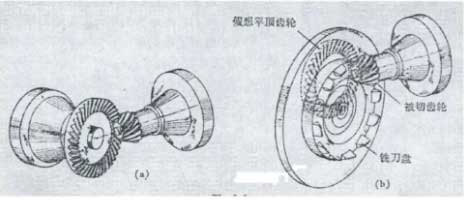
The processing principle of spiral bevel gear is shown in the figure. Its profile wheel is an imaginary flat top gear, and the milling cutter head is a spiral bevel gear tooth on the profile wheel. When the profile wheel is combined with the spiral bevel gear whistle to be cut, the cutter head will cut the spiral bevel gear tooth on the wheel. How to process the big wheel and the small wheel and make them mesh correctly is the main problem to be solved in the tooth cutting calculation. On this point, many experts and scholars at home and abroad have done a lot of research and published many papers and monographs. Especially for the shrink tooth spiral bevel gear and hypoid gear, because the big wheel and the small wheel processed by the flat top profile generating wheel are not in common in theory, it is very complex to calculate their normal and curvature at the calculation point, and to make contact analysis of the tooth surface, so it is difficult to get the ideal results when they are applied to the reality. In recent years, especially with the popularization of CNC milling machine and dry cutting technology, the face hobbing machining method of Oerlikon gear system and the cycle paloid machining method of Klingeinberg have developed rapidly in China. They are all Cycloid Teeth with equal height, not only the calculation of cutting teeth is simple, but also the contact area is better than the contraction teeth. After the research, it is found that in the processing of small batch products, especially the processing of large-scale spiral bevel gears, the use of circular arc contour teeth is an ideal choice.

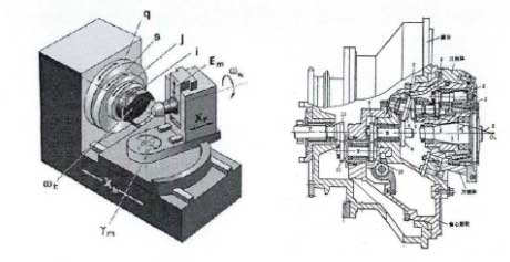
The machining of spiral bevel gears with equal height teeth, because they can be completely common in theory, does not need to calculate the normal curvature of the theoretical tooth surface as complicated as the shrinking teeth. It only needs to simply boil down to three basic conditions: equal pressure angle, equal helix angle and a curvature difference of the cutter head radius. Before discussing these three basic conditions in detail, the adjustment parameters of the spiral bevel gear cutting machine are introduced. Figure is the basic structure of spiral bevel gear machining machine tool. The position of cutter head on the machine tool is called cutter position, and the position of spiral bevel gear on the machine tool is called wheel position. It can be seen from the figure that the cutter head is installed on the cutter tilt body, the cutter tilt body is installed on the cutter turn body, the cutter turn body is installed on the eccentric drum, and the eccentric drum is installed on the shaking table. The cutter position can be completely determined by four parameters:

(1) Tool inclination angle
The angle of the inclination body is called the inclination angle. When it is not equal to 0, the axis of the cutter head is not parallel to the axis of the profile wheel represented by the cradle, and the profile wheel is called the cone profile wheel. When it is equal to 0, the axis of the cutter head is parallel to the axis of the profile wheel represented by the cradle, and then the profile wheel is called flat top profile wheel.
(2) Knife angle
The turning angle of the cutter body is called the turning angle of the cutter. Its function is to adjust the inclination of the cutter head to the required direction.
(3) Radial cutter position
The distance from the center of the cutter head (the intersection of the cutter tip plane and the cutter axis) to the axis of the generating wheel is called the radial cutter position. On the mechanical toothing machine, it is adjusted by eccentric drum.
(4) Angle knife position
The angle of the rocker at the rolling center is called the angle cutter position.
It can also be seen from the figure that there is a bed saddle on the machine tool that can move along the axis of the shaking table, a turntable that can rotate in a sector on the bed saddle, a box that can move along the axis of the workpiece on the turntable, a workpiece box that can move up and down on the box, and the processed spiral bevel gear is installed on the workpiece box. Obviously, the wheel position can also be completely determined by the following parameters.
(1) Bed.
The position of the saddle on the machine is called the bed, and its value will affect the depth of the teeth.
(2) Installation angle of wheel blank:
The angle of sector turntable is called installation angle of wheel blank, which is used to adjust the root cone angle of spiral bevel gear.
(3) Horizontal wheel position
The position of the box that can move along the axis of the workpiece is called the horizontal wheel position.
(4) Vertical wheel position
The position of the box where the spiral bevel gears are installed is called the vertical wheel position.
(5) Roll ratio
During spiral bevel gear processing, the generating wheel and workpiece rotate along their respective axes, and their transmission ratio is called roll ratio.
The above parameters are obtained for the mechanical gear milling machine. The current CNC gear milling machine is designed to simulate the mechanical gear milling machine. Its processing theory is exactly the same as the mechanical gear milling machine, so the above parameters are still valid.

