
At present, there are many machining methods of circular tooth profile cylindrical gears that can be queried, such as double-edge rotary cutter head milling, single-edge rotary milling cutter head machining, parallel linkage mechanism machining, CNC vertical milling machine machining, etc., but the most common machining methods are rotary cutter head method and parallel linkage method. Compared with parallel linkage mechanism, rotary cutter head milling has higher gear processing efficiency and can also ensure accuracy. In terms of system stiffness, maximum cutting speed, rationality of machining tooth shape, and whether it can process hard tooth surface, rotary cutter head method has better technological performance, so it is currently the most widely used. However, this method will leave machining marks on the surface of cylindrical gears with circular tooth profile, and further finishing is required.
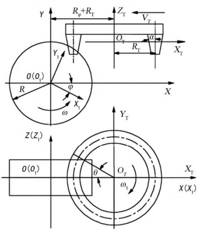
The principle of gear milling with rotary cutter head is shown in Figure 1. In the process of gear machining, there are three motions: high-speed rotary cutting motion of cutter head, rotary motion of gear blank around the center and horizontal movement of cutter head, and feed motion of cutter head to ensure complete machining. The cutter head is installed on the main shaft of the machine tool, and the gear blank is installed on the machine tool. When the machine tool is working, the cutter head and the gear blank will move at the given speed, so:
VT = VR
Where: VT is the moving speed of cutter head in X direction; VR is the rotation speed on the pitch circle of the gear blank.
After machining a complete gear, use the indexing mechanism to finish the indexing of the gear blank, and continue to process the next gear surface until a complete gear is processed.
Establish the coordinate system as shown in Figure 1, S0 (X Y Z) is the static coordinate system, S1 (X1Y1Z1) is the dynamic coordinate system fixedly connected with the tooth, ST (XT YTZT) is the coordinate system fixedly connected with the cutter head, and the speed VT=R 獉 ω Translate relative to the S0 coordinate system, R is the radius of the indexing circle of the gear blank, the average developing radius of the tool is Rt, the right inner blade is used to generate the convex tooth surface, the left outer blade is used to generate the concave tooth surface, the displaying radius of the inner and outer blades are Rn=R – π m/4 and Rm=R+π m/4 respectively, and the radius of the convex tooth surface of the gear is slightly smaller than the radius of the concave tooth surface.
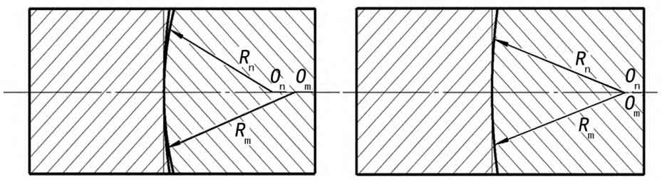
According to the machining principle, there is a difference in the radius of the cutter head for machining the convex tooth surface and the concave tooth surface, which causes the width of the tooth groove at the middle section to be slightly smaller than the width of the tooth groove at the gear end face. When a pair of gear pairs processed by the above principles are engaged, the convex surface of one gear is in contact with the concave surface of the other gear. Due to the different radius of tooth surface development, the meshing state of the gear is shown in Figure 2. At this time, the gear is in point contact meshing. As shown in Figure 3. The ideal meshing state of circular arc tooth line cylindrical gear is line contact meshing. At this time, the radius of the convex tooth surface of the gear is equal to the radius of the concave tooth surface. The tooth profile along the tooth width direction is an involute tooth profile. The tooth line is a part of the arc. The circumferential and normal tooth width of the gear are equal everywhere. The contact line of the gear pair is a space curve.