1. Formation analysis of hypothetical plane forming wheel
The concept of hypothetical plane forming wheel is that there is a plane gear moving on the same axis as the shaking table of the machine tool, which can continuously mesh with the processing gear under the rotation of the shaking table of the machine tool. As shown in Figure 1, the profile of the moving hypothetical production gear is the curve profile of the cutting process corresponding to the cutting edge of the milling cutter on the shaking table of the machine tool. In the whole cutting process, the cutting edge of spiral bevel gear milling cutter can quickly cut out the overall contour on the surface of the processed gear. According to the machining path of the cutting edge of the milling cutter, the gear teeth of the imaginary plane generating wheel are represented. The gear can be machined through the mutual transmission between the workpiece and the imaginary plane generating wheel. And the end face cone angle, tooth root cone angle and indexing cone angle of equal height spiral bevel gear are all consistent.
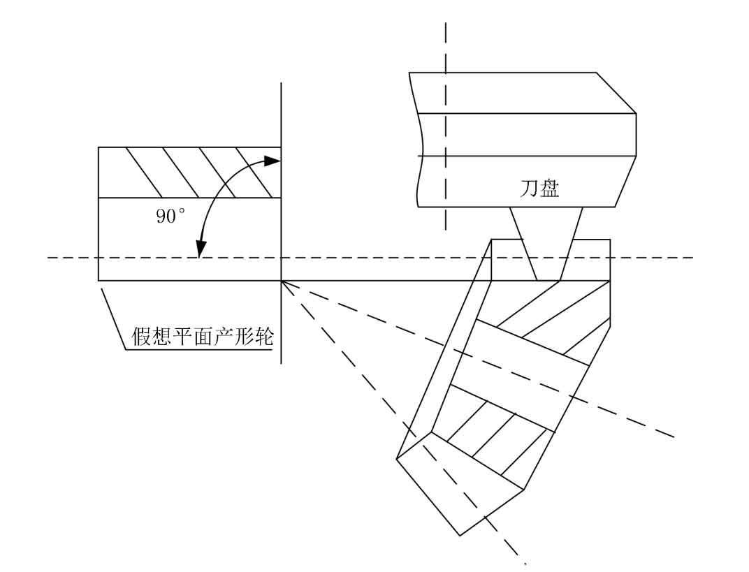
The gears of equal height spiral bevel gears are usually machined with sharp tooth cutter head. In the cutting movement, the cutter head is equivalent to two groups of rotation all the time: first, it rotates continuously around the center line of the cutter head. At the same time, the cutter head rotates around the centerline of the imaginary plane forming wheel.
2. Formation analysis of extended epicycloid
The machining of spiral bevel gear with equal height teeth must be completed by using the end milling cutter head equipped with a certain number of cutter strips. Each group of cutter strips cuts one gear gap of the gear blank, and a group of adjacent cutter strips cuts another gear gap of the gear blank. If the cutter head is equipped with ZW cutter strips, the workpiece rotates to cut the ZW gear clearance every time the cutter head rotates. When the cutter head rotates continuously, the gear blank must also rotate continuously to separate the clearance of the equal height spiral bevel gear. Therefore, the equal height spiral bevel gear is cut continuously and there is no need to cut the gear intermittently.
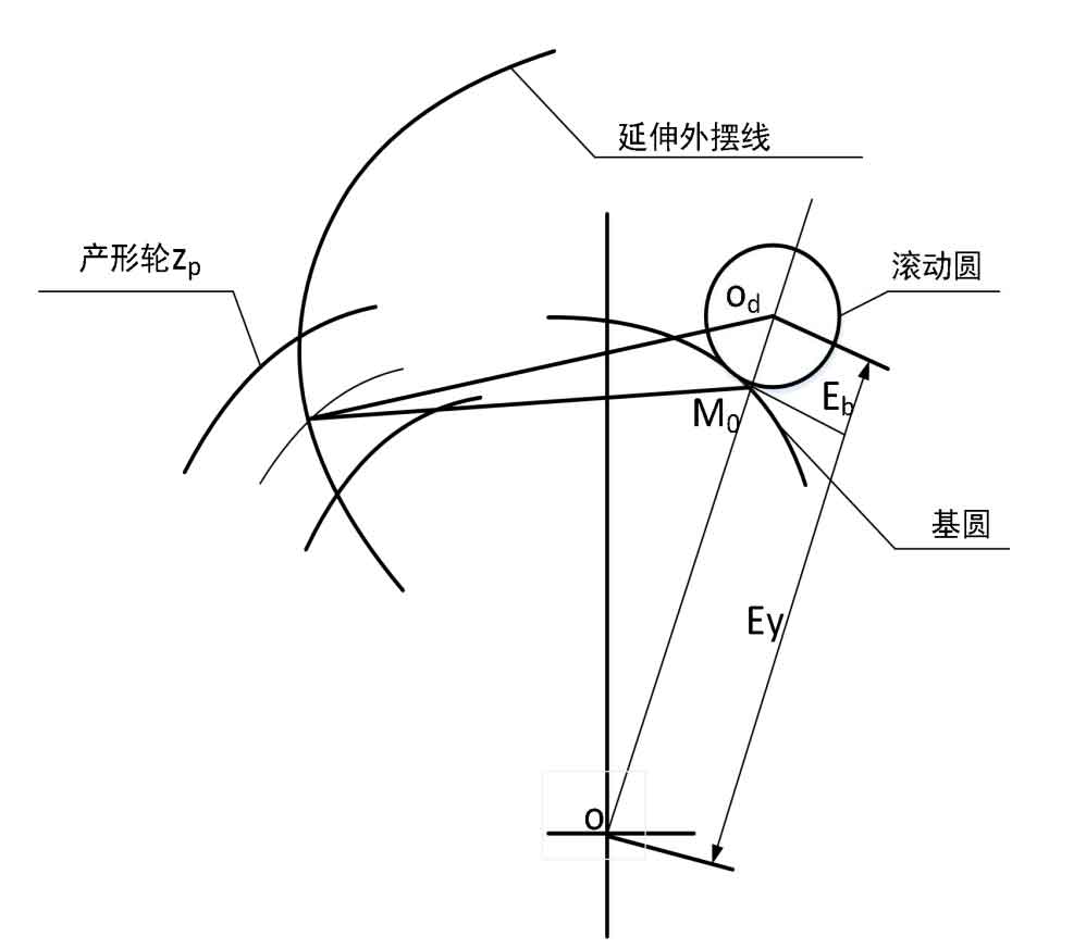
Suppose that when a Z w set of blades rotates around the generating wheel, the generating wheel with the same number of Z P teeth moves ZW / Z P rounds. On the straight line ODO between the rotation midpoint of the cutter head and the rotation midpoint of the generating wheel, there will be a point M0 in contact with the rolling circle. On the contact point, the speed of their relative position is zero, and the point M0 is the rotation center of the contact between the blade and the contour spiral bevel gear. When the generating wheel does not rotate, the corresponding rotation of the cutter head around the generating wheel takes the point M0 as the center. When Z W and Z P are fixed values, the length of points M0 to O and OD will also be fixed values, that is, EB / ey = ZW / Z P. therefore, the rotation of the production wheel corresponding to the cutter head is a pure rolling motion around the rolling circle with radius EB and the base circle with radius ey. Therefore, the cutting path of the blade is the extended epicycloid. As shown in Figure 2.
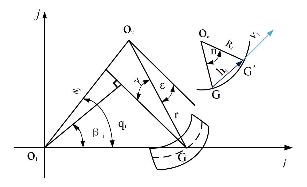
3. Cutter head cutting surface equation
Using the tooth surface hobbing method to cut the equal height spiral bevel gear is that when the cutter head cuts the equal height spiral bevel gear around its own axis, it will also rotate around the axis of the forming wheel. As shown in Fig. 3, it is the schematic diagram of cutter head cutting movement. O1 is the intersection of generating wheel axis and indexing plane, O2 is the intersection of cutter head axis and generating wheel plane, G is the calculation point of cutting, G ‘is any point on the cutting edge, let the center angle corresponding to G and G’ be n, V1 is the tangent unit vector of G ‘on the arc cutting edge, and V1 points to the direction of tooth top. H1 is the unit vector from G to G ‘, and R1 is the cutting edge radius of the blade. When G ‘g points to the top of the blade, R1 is positive and N is positive. When g’g points to the tool tip direction, R1 is a negative value, and N is a negative value. ε Is the pressure angle of the cutter teeth, γ Is the lead angle of the cutter head teeth, S1 is the radial tool position for gear cutting, and Q1 is the angular tool position for gear cutting. The position of the cutter head Q1 at the time of machine tool adjustment is determined by the position of the cutter head S1. R is the radius of the cutter teeth of the cutter head on the plane of the generating wheel, β 1 is the helix angle of the processed equal height spiral bevel gear.