The virtual simulation process is basically the same as the actual machining process. By adjusting the parameters of the NC machine tool, the motion relationship between the helical gear shaper cutter and the workpiece is obtained, and the control of the motion axis relationship between the helical gear shaper cutter and the workpiece is realized. The helical offset non orthogonal surface gear can be processed through the cooperative movement of various components of the NC machine tool.
1. Build the model of gear shaping machine tool
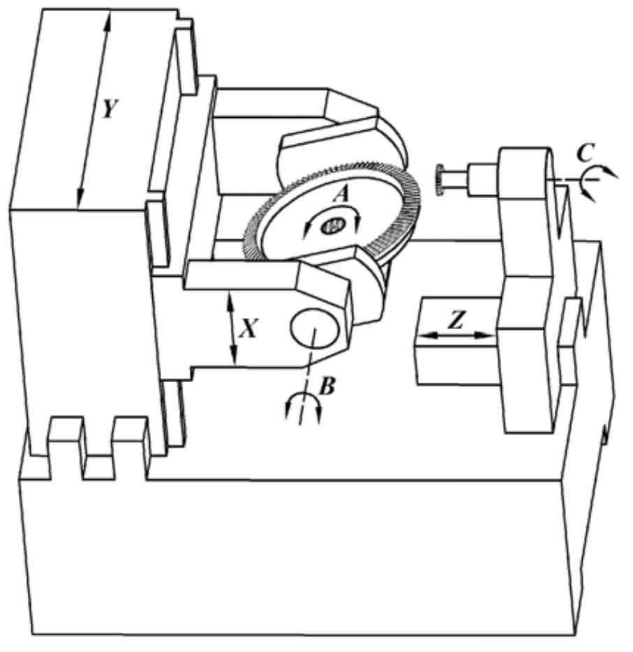
According to the six movements involved in face gear machining, the NC machine tool model shown in Figure 1 is built. The machine tool includes two transmission chains: spindle transmission chain and workpiece transmission chain. The main shaft transmission chain includes: the x-axis for controlling the tooth depth feed, the y-axis for adjusting the offset distance of the spiral gear shaper cutter relative to the central axis of the face gear, the z-axis for controlling the reciprocating motion of the spiral gear shaper cutter, and the c-axis for controlling the additional rotation and indexing of the spiral gear shaper cutter. The workpiece transmission chain includes: b-axis controlling the staggered angle and a-axis of workpiece rotation axis.
Firstly, set the attachment relationship of each mechanism component of the machine tool on the VERICUT project tree; Then, the model of each part of the machine tool is established according to the required size parameters in SolidWorks software and saved in STL format; Finally, the model of each part is introduced into the corresponding position of the machine tool, that is, the construction of the gear shaper machine tool is completed.
2. Simulation process and results
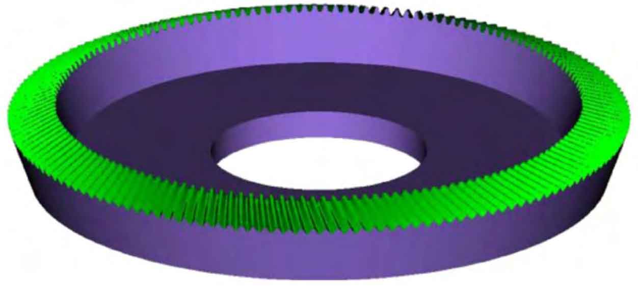
The simulation machining of face gear shaping can be carried out by importing the prepared program: adjust the spiral gear shaping cutter to the appropriate initial position, and the workpiece rotates clockwise 20 ° around axis B, so that the staggered angle between the spiral gear shaping cutter shaft and the face gear is 110 °; The spiral gear shaper cutter adds the rotation of the c axis while cutting the Z axis, so that the blade feeds along the spiral line to form the spiral tooth surface; Lift up the x-axis to complete the movement of the knife; The tool returns to the initial cutting position and completes the tool withdrawal movement; In the process of gear shaping, there is a fixed coupling relationship between the rotation of axis C and axis A, that is, the indexing development movement between the spiral gear shaping cutter and the blank is carried out according to the ratio of the number of teeth between them. Cycle the above cutting steps to obtain the face gear model as shown in Figure 2, and save the VERICUT gear shaping simulation results in STL format.