
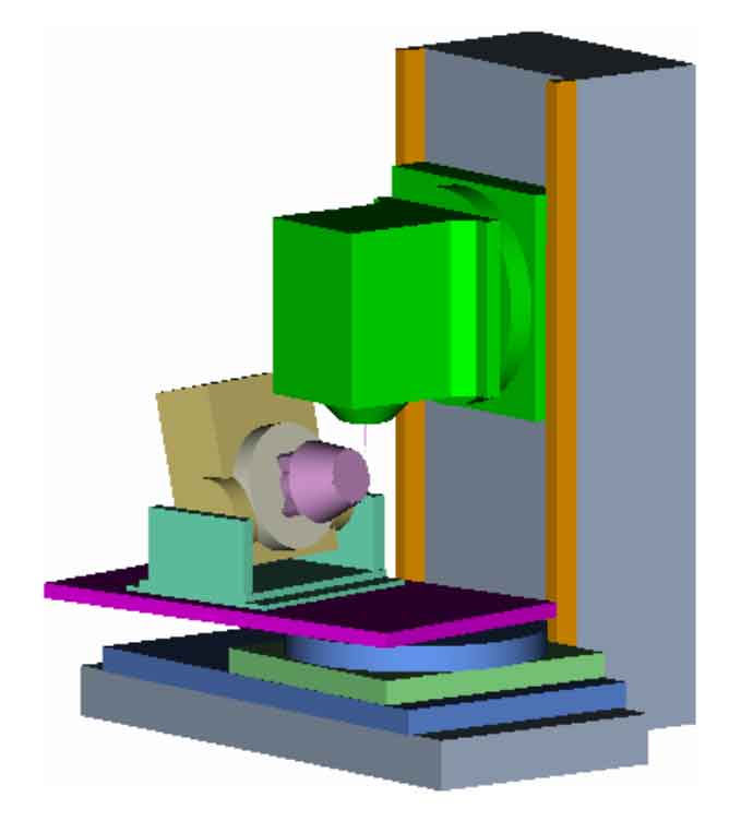
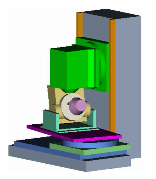
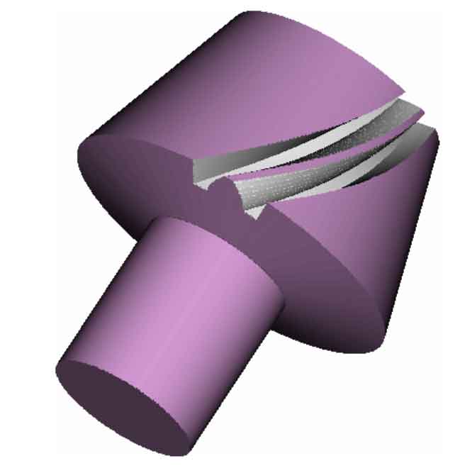
Based on the establishment of the simplified model, gear blank model and tool model of the two-axis linkage gear cutting machine tool, call the sin840d control system built in VERICUT, and add the prepared NC machining program to the NC program file of the simulation machining project tree. Finally, the two-axis linkage milling simulation of spiral bevel gear can be realized by clicking the control simulation button. The initial feed position of concave tooth surface is shown in Figure 1, while the initial position of convex tooth surface processing is shown in Figure 2. The first tooth of spiral bevel gear can be machined by the first cycle statement of NC machining program, as shown in Figure 3. Then, through the cycle of indexing and gear processing statements, the right-hand spiral bevel gear with 15 teeth and 9 modulus can be milled, as shown in Fig. 4.
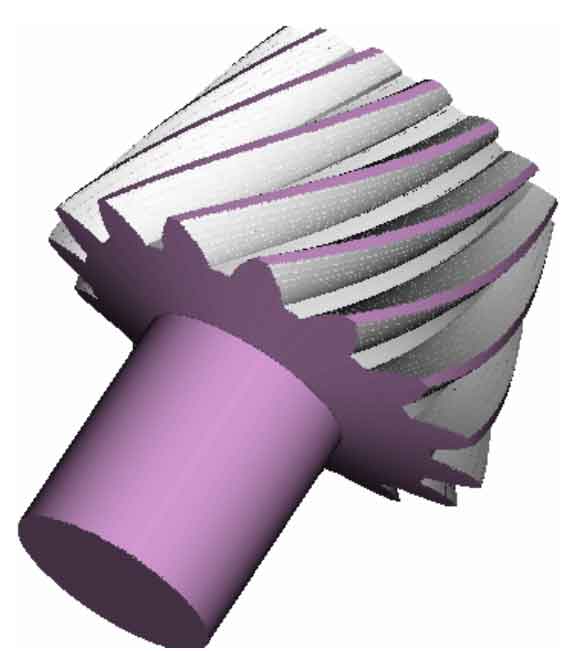
Through the two-axis linkage computer gear cutting simulation of spiral bevel gear, the results show that:
① The designed spiral bevel gear cutting machine tool can realize all the movements required in the process of two-axis linkage cutting;
② There is no interference, collision, over cutting and under cutting of tooth surface in the whole cutting process of gear teeth, which proves the correctness of the NC machining program;
③ Finally, the expected spiral bevel gear model is cut, which proves the feasibility of the new method of two-axis linkage gear cutting.