
I began my investigation from a practical concern: when lubrication in a mechanical transmission becomes insufficient, the contacting surfaces of the transmission elements wear rapidly, and the entire drive train can lose efficiency, generate excessive heat, and eventually fail. Screw gears, especially the worm-drive form used in compact reducers, are particularly sensitive to lubrication because their meshing surfaces combine rolling and large sliding motion. This sliding motion is useful for achieving high reduction ratios in a small volume, but it also makes the formation and retention of a stable lubricating film difficult. I therefore focused on a new approach: using a magnetic fluid as a controllable lubricant and designing a magnetic circuit that can hold the magnetic fluid in the meshing zone of screw gears.
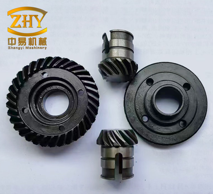
I use the term screw gears throughout this work to describe the worm-and-wheel transmission that I studied. A screw gear pair transmits motion between two non-parallel, usually orthogonal, shafts. This configuration allows a single stage to provide a very large reduction ratio, smooth motion, low noise, and self-locking under certain lead-angle conditions. At the same time, screw gears suffer from low efficiency and severe heat generation because the relative sliding velocity at the tooth contact is high. The lubricant must therefore do more than reduce friction; it must also remove heat, prevent scuffing, limit wear, and remain in the contact zone under centrifugal and squeezing actions.
My central idea was to combine the properties of a magnetic fluid with a closed magnetic circuit built around a screw gear reducer. A magnetic fluid is a stable colloidal suspension of magnetic nanoparticles in a carrier liquid. The particles are typically about ten nanometers in diameter and are coated with a surfactant to prevent agglomeration. Because the particles are superparamagnetic, the fluid responds strongly to an external magnetic field but does not retain significant magnetization after the field is removed. This behavior makes it possible to position and retain the lubricant by magnetic force while preserving its liquid-like flow when the field is removed or reduced.
I structured the work into four connected parts. First, I designed two magnetic circuit concepts for a screw gear reducer and compared them by finite-element simulation. Second, I verified the magnetic circuit by observing magnetic fluid behavior in a transparent model. Third, I designed and built a screw gear test rig with controllable speed, load, and temperature measurement. Fourth, I performed lubrication experiments using a diester base liquid and two magnetic fluids with different saturation magnetization values. I evaluated the results by measuring the temperature rise of the screw gear shaft and by examining the wear morphology of the wheel teeth.
The main quantities that I used to describe the magnetic circuit follow directly from classical magnetic circuit theory. The magnetic flux density is related to the magnetic field strength by the constitutive relation:
$$ \mathbf{B} = \mu \mathbf{H} = \mu_r \mu_0 \mathbf{H} $$
where \(\mathbf{B}\) is the magnetic flux density, \(\mathbf{H}\) is the magnetic field strength, \(\mu_0\) is the permeability of free space, and \(\mu_r\) is the relative permeability of the material. For a magnetic circuit, I used the magnetomotive force, the magnetic reluctance, and the magnetic flux in a form analogous to Ohm’s law. The magnetomotive force produced by a coil is:
$$ \mathcal{F} = N I $$
where \(N\) is the number of turns and \(I\) is the current. For a permanent magnet, the magnetomotive force is provided by the equivalent magnetic source of the magnet. The reluctance of a uniform magnetic path is:
$$ \mathcal{R} = \frac{L}{\mu S} $$
where \(L\) is the path length and \(S\) is the cross-sectional area. The magnetic flux is then:
$$ \Phi = \frac{\mathcal{F}}{\mathcal{R}} $$
For a branched magnetic circuit, I applied the magnetic Kirchhoff laws. The first law states that the algebraic sum of magnetic fluxes at a node is zero:
$$ \sum_{i=1}^{n} \Phi_i = 0 $$
The second law states that the algebraic sum of magnetic potential drops around a closed loop equals the algebraic sum of magnetomotive forces:
$$ \sum_{i} H_i l_i = \sum_{j} N_j I_j $$
These equations formed the basis for my permanent-magnet circuit design. I also compared the magnetic circuit to an electric circuit, because this analogy helped me choose the geometry and materials. The correspondence is summarized in Table 1.
| Electric circuit quantity | Magnetic circuit quantity | Relationship |
|---|---|---|
| Current | Magnetic flux | \(\Phi = B S\) |
| Voltage | Magnetomotive force | \(\mathcal{F} = N I\) |
| Conductance | Permeance | \(\mathcal{P} = \mu S / L\) |
| Resistance | Reluctance | \(\mathcal{R} = L / (\mu S)\) |
| Ohm’s law | Magnetic Ohm’s law | \(\Phi = \mathcal{F} / \mathcal{R}\) |
| Kirchhoff current law | Flux continuity | \(\sum \Phi_i = 0\) |
| Kirchhoff voltage law | Ampere loop law | \(\sum H_i l_i = \sum N_j I_j\) |
I first reviewed the common permanent-magnet circuit arrangements before selecting a geometry for screw gears. In a general magnetic circuit, the permanent magnet can be placed in different positions relative to the air gap and the neutral plane. Some common arrangements include a magnet whose neutral plane coincides with the symmetry plane of the circuit, two magnets with neutral planes perpendicular to the gap, a single magnet with one pole forming the gap, two magnets with the gap between their pole faces, and a single magnet with two gaps at the pole faces. Each arrangement has different leakage and reluctance characteristics. For a screw gear reducer, the available space is limited by the housing, bearings, and end caps, so the design must avoid interfering with the rotating shafts while still placing a strong field at the meshing region.
The requirements for my magnetic circuit design were straightforward but strict. The circuit had to create a sufficiently high magnetic flux density in the meshing zone of the screw gears. It had to keep the magnetic fluid near the contact region without causing the fluid to be thrown away at high speed. It had to avoid contact with the rotating worm shaft and worm wheel. It had to minimize changes to the original reducer structure. It had to allow assembly and disassembly. It also had to use materials that would not degrade the mechanical strength or wear resistance of the screw gears. Table 2 lists these requirements and the way I addressed them.
| Design requirement | My approach | Reason |
|---|---|---|
| High field in meshing zone | Closed magnetic loop through the worm, wheel, and conductive bars | Reduces leakage and concentrates flux at the contact |
| Fluid retention | Field gradient directed toward the meshing teeth | Holds magnetic fluid against centrifugal loss |
| No interference | Small air gaps between magnets and rotating parts | Allows free rotation of the screw gears |
| Minimal housing modification | Use end caps with magnet pockets and conductive strips | Preserves the original reducer structure |
| Simple assembly | Cylindrical magnets and removable end caps | Allows testing with different magnet strengths |
| Material compatibility | Steel and cast iron for magnetic paths | Provides both strength and permeability |
The screw gear reducer that I used had a center distance of 40 mm, a single-start worm, and a wheel with 30 teeth. The gear ratio was therefore 30:1. The worm and wheel materials could be selected as steel or cast iron for the magnetic simulation, but for the final wear tests I used steel screw gears because steel provides better magnetic flux guidance and higher strength. I designed two magnetic circuit schemes. In the first scheme, I used a T-shaped connector, a magnetic yoke, and two tile-shaped permanent magnets. The tile magnets were radially magnetized and placed symmetrically around the worm. A small gap of 0.5 mm separated the magnets from the worm surface. In the second scheme, I used a closed magnetic loop. Cylindrical permanent magnets were inserted into modified end caps. Conductive magnetic strips connected the magnets to the worm and wheel shafts. The magnetic path then passed through the worm, across the meshing teeth, through the wheel, and back through the conductive strips and magnets. This closed loop was intended to reduce magnetic leakage and concentrate flux exactly where the screw gears contact each other.
I compared the two schemes by finite-element analysis using a three-dimensional direct-current magnetic solver. I imported the solid models, assigned material properties, set the permanent magnet magnetization direction, generated a tetrahedral mesh, and solved the magnetic field. The solver used adaptive mesh refinement. I set the maximum number of passes and the percent error so that the solution converged reliably. The materials included NdFe35 for the permanent magnets, iron for the magnetic paths, steel45 for the steel screw gears, and cast iron for the cast-iron wheel. Table 3 summarizes the material assignments that I used in the simulation.
| Component | Material | Relative permeability or magnetic property |
|---|---|---|
| Permanent magnet | NdFe35 | \(B_r\) adjusted to obtain different surface fields |
| Magnetic yoke and strips | Iron | \(\mu_r \approx 4000\) |
| Worm | Steel45 | Nonlinear \(B\)-\(H\) curve |
| Wheel option A | Cast iron | Nonlinear \(B\)-\(H\) curve |
| Wheel option B | Steel45 | Nonlinear \(B\)-\(H\) curve |
| Housing and non-magnetic parts | Non-magnetic | \(\mu_r \approx 1\) |
The simulation results showed a clear difference between the two schemes. In the first scheme, the magnetic field was strong near the tile magnets but diverged rapidly as it approached the meshing zone. At the screw gear contact, the field was too weak to retain a useful amount of magnetic fluid. In the second scheme, the closed loop carried the flux through the worm, the wheel, and the conductive strips. The meshing zone became a high-flux-density region. The magnetic flux density at the contact teeth was much higher than in the surrounding space. This was exactly the behavior I wanted, because the magnetic fluid would be pulled toward the highest field gradient and held between the contacting screw gear teeth. Table 4 compares the two schemes.
| Feature | Scheme 1: open yoke with tile magnets | Scheme 2: closed loop with end-cap magnets |
|---|---|---|
| Magnet type | Two radially magnetized tile magnets | Two axially magnetized cylindrical magnets |
| Magnetic path | Partially open through air | Closed through worm, wheel, magnets, and strips |
| Field at meshing zone | Weak and diffuse | Strong and localized |
| Leakage | High | Low |
| Housing modification | Additional internal support | Modified end caps and external strips |
| Assembly complexity | Moderate to high | Low to moderate |
| Overall suitability for screw gears | Poor | Good |
I selected the closed-loop scheme for further study. I then examined how the wheel material affected the magnetic field distribution. I compared a cast-iron wheel with a steel45 wheel while keeping the steel45 worm. The magnetic flux density along a path through the middle plane of the screw gear pair showed that both materials produced a high-field region near the meshing point. The average flux density in that region was approximately 300 mT, with a maximum near 370 mT. The steel45 wheel gave a slightly higher field at high flux density because its magnetization curve was more favorable in that range. The cast-iron wheel performed better only at low flux density. These results indicated that steel45 was a suitable choice for both members of the screw gear pair when magnetic flux guidance and mechanical strength were both important.
I also studied how the external magnet strength affected the field in the meshing zone. I prepared three permanent magnets with measured surface flux densities of 150 mT, 250 mT, and 350 mT. I adjusted the remanence parameter in the material model so that the simulated surface field matched the measured value. The simulation showed that the high-flux-density region expanded as the external magnet strength increased. Along a semicircular path that passed through the screw gear contact, the maximum flux density was approximately 40 mT for the 150 mT magnet, 70 mT for the 250 mT magnet, and 100 mT for the 350 mT magnet. The relationship was nearly linear, as shown in Table 5. I also measured the actual field in the tooth gap with a gauss meter. The measured and simulated values agreed within 17 mT, which gave me confidence that the finite-element model was reliable.
| Surface field of permanent magnet (mT) | Simulated maximum field in meshing zone (mT) | Measured field in tooth gap (mT) | Absolute difference (mT) |
|---|---|---|---|
| 150 | 40 | approximately 35 | less than 17 |
| 250 | 70 | approximately 62 | less than 17 |
| 350 | 100 | approximately 91 | less than 17 |
Before running the lubrication experiments, I verified the magnetic circuit with a transparent acrylic model of a screw gear reducer. The acrylic housing allowed me to see the meshing region directly. I added a small amount of magnetic fluid and rotated the screw gears at different speeds. Without a magnetic field, the fluid was quickly thrown away from the contact and only a thin residue remained on the teeth. With the magnetic circuit installed, the magnetic fluid clustered near the meshing zone. At low speed, it formed a dense, connected body on the teeth. At higher speed, the fluid without a field splashed away first, while the fluid in the magnetic field remained attached to the contact region for a longer time. This observation confirmed that the closed magnetic circuit could indeed position and retain magnetic fluid in the working zone of screw gears.
Once the magnetic circuit was validated, I designed and built a screw gear test rig. I chose an open power-flow configuration because it is simple, easy to control, and suitable for small and medium power tests. The test rig consisted of a driving module, a screw gear reducer, a loading module, a measurement module, and a support frame. The driving module was a stepper motor. I selected a stepper motor because its speed can be controlled precisely by pulse frequency and its output torque is stable at low and medium speeds. The loading module was a magnetic powder brake. A magnetic powder brake produces a controllable torque through a magnetic powder coupling, and its torque can be adjusted smoothly by changing the excitation current. The measurement module used a non-contact infrared temperature sensor to record the surface temperature of the screw gear shaft. Table 6 lists the main components of the test rig.
| Module | Component | Key specification | Function |
|---|---|---|---|
| Drive | Stepper motor | Rated speed 1000 rpm, output torque 2.2 N·m, shaft diameter 8 mm | Provides controlled input speed |
| Drive control | Stepper driver | DC 16–70 V, microstep 800–51200 | Converts pulses to motor motion |
| Signal source | Pulse generator | Adjustable frequency and duty cycle | Sets motor speed |
| Load | Magnetic powder brake | Rated torque 50 N·m, excitation current 1.8 A | Applies controllable load torque |
| Load control | Tension controller | 24 V input, manual adjustment | Regulates brake torque |
| Temperature | Infrared sensor | Range −50 to 320 °C, resolution 0.02 °C | Measures shaft surface temperature |
| Coupling | Flexible couplings | Compensates small misalignments | Transmits torque between modules |
| Support | Brackets and base plates | Stainless steel | Positions and aligns components |
The stepper motor speed was related to the pulse frequency by the driver microstep setting. If the motor has 200 full steps per revolution and the driver uses a microstep factor \(x\), then the input pulse frequency \(f\) and the motor speed \(n\) are related by:
$$ n = \frac{60 f}{200 x} $$
I used this relation to set the input speed of the screw gears. The load torque was controlled by the tension controller, which adjusted the excitation current of the magnetic powder brake. The output voltage of the controller was proportional to the input voltage according to:
$$ u_o = \eta u_i $$
where \(\eta\) is the percentage set by the controller knob. This made it possible to vary the load torque in a repeatable way.
I designed the mounting brackets and base plates in a three-dimensional computer-aided design environment. I imported the screw gear reducer, the stepper motor, and the magnetic powder brake, and then arranged them so that their shafts were aligned. I used a flexible coupling between the stepper motor and the screw gear reducer, and a separable coupling between the reducer and the magnetic powder brake. I machined the brackets from stainless steel to reduce corrosion and maintain stiffness. I placed the infrared temperature sensor above the worm shaft and opened a small observation window in the reducer housing so that the sensor could see the shaft surface without touching it. The assembled test rig allowed me to change speed, load torque, magnetic field strength, and lubricant type independently.
For the lubrication experiments, I prepared three lubricants: a diester base liquid, a magnetic fluid with a saturation magnetization of 200 Gs, and a magnetic fluid with a saturation magnetization of 440 Gs. The magnetic fluids were based on a diester carrier liquid and contained Fe\(_3\)O\(_4\) nanoparticles with an average diameter of about 10 nm. The particle concentrations and densities differed because the magnetic particle content was different. Table 7 lists the lubricant properties.
| Lubricant | Fe\(_3\)O\(_4\) content | Particle size | Density | Saturation magnetization |
|---|---|---|---|---|
| Diester base liquid | 0 | not applicable | 0.969 g/cm\(^3\) | 0 |
| Magnetic fluid A | 21% | 10 nm | 1.10 g/cm\(^3\) | 200 Gs |
| Magnetic fluid B | 53% | 10 nm | 1.33 g/cm\(^3\) | 440 Gs |
I used the same amount of lubricant in every test: 0.1 mL. Before assembly, I cleaned the screw gear surfaces by ultrasonic cleaning and drying. After assembly, I mounted the reducer on the test rig, added the lubricant, and started the test. I recorded the shaft surface temperature continuously until it reached a steady value. After the test, I disassembled the reducer, cleaned the screw gears in heated acetone at 50 °C, rinsed them, and dried them. I then cut the wheel teeth from the wheel and examined the surfaces with an optical microscope and a three-dimensional surface profiler. The experimental variables are summarized in Table 8.
| Test series | Input speed (rpm) | Load torque (N·m) | Magnetic field | Lubricant |
|---|---|---|---|---|
| Speed effect | 300, 600, 900 | 5.0 | 350 mT magnet | Diester and 440 Gs magnetic fluid |
| Load effect | 600 | 2.5, 5.0, 7.5 | 350 mT magnet | Diester and 440 Gs magnetic fluid |
| External field effect | 300, 600, 900 | 2.5, 5.0, 7.5 | 150, 250, 350 mT magnets | 440 Gs magnetic fluid |
| Saturation effect | 300 and 600 | 7.5 | 150, 250, 350 mT magnets | 200 Gs and 440 Gs magnetic fluids |
In the speed-effect tests, I used the number of wheel tooth meshing cycles as the horizontal variable rather than time. This was important because the screw gears do not mesh at the same frequency when the input speed changes. The number of meshing cycles per wheel tooth is:
$$ N = \frac{n_i Z_1}{Z_2} t $$
where \(n_i\) is the input speed, \(Z_1\) is the number of worm starts, \(Z_2\) is the number of wheel teeth, and \(t\) is the test time. This definition allowed me to compare wear and temperature histories on a common basis.
At an input speed of 300 rpm, the diester and the magnetic fluid both showed a rapid temperature rise during the first 200 meshing cycles. After that, the temperature reached a steady value near 35 °C for both lubricants. At this low speed, the magnetic field did not produce a large additional benefit because the centrifugal loss was small and even the base liquid could remain in the contact region. At 600 rpm, the difference became clear. The diester reached a steady temperature of about 44 °C, while the magnetic fluid reached only about 36 °C. The magnetic fluid therefore reduced the temperature rise by roughly 8 °C. At 900 rpm, the diester reached about 48 °C, while the magnetic fluid reached about 40 °C. The benefit was still significant, although the magnetic fluid also heated up more than at lower speeds. Table 9 summarizes the steady temperatures.
| Input speed (rpm) | Diester steady temperature (°C) | Magnetic fluid steady temperature (°C) | Temperature reduction (°C) | Relative reduction |
|---|---|---|---|---|
| 300 | 35 | 35 | 0 | 0% |
| 600 | 44 | 36 | 8 | 18.2% |
| 900 | 48 | 40 | 8 | 16.7% |
The wear morphology supported the temperature results. With the diester lubricant, the wheel tooth surfaces developed wider arc-shaped scratches and darker wear patches as the speed increased. The scratches changed from narrow lines to ploughing grooves. With the magnetic fluid, the wear marks became wider but not much deeper. The three-dimensional surface profiles showed that the maximum wear depth of the magnetic-fluid-lubricated teeth remained nearly constant as speed increased, while the diester-lubricated teeth became progressively rougher. This indicated that the magnetic fluid maintained a more stable lubrication state in the screw gear contact at higher speeds.
I then studied the effect of load torque while keeping the input speed at 600 rpm. At 2.5 N·m, the diester reached about 36 °C and the magnetic fluid reached about 34 °C. At 5.0 N·m, the diester reached about 42 °C, while the magnetic fluid remained near 35 °C. At 7.5 N·m, the diester rose above 54 °C, and the magnetic fluid rose to about 45 °C. The temperature increase with load was much steeper for the diester than for the magnetic fluid. This showed that the magnetic fluid improved the load-carrying capacity of the lubricating film and reduced frictional heating in the screw gear contact. Table 10 lists the steady temperatures for the load tests.
| Load torque (N·m) | Diester steady temperature (°C) | Magnetic fluid steady temperature (°C) | Temperature reduction (°C) |
|---|---|---|---|
| 2.5 | 36 | 34 | 2 |
| 5.0 | 42 | 35 | 7 |
| 7.5 | 54 | 45 | 9 |
The wear surfaces after the load tests showed a similar trend. With the diester, the tooth surface scratches became deeper and wider as the load increased. At 7.5 N·m, the diester-lubricated teeth showed large pits, detached particles, and block-like missing regions. This was evidence of scuffing and severe adhesive wear. With the magnetic fluid, the teeth developed mainly shallow arc-shaped scratches. At the highest load, the magnetic fluid still showed some wear, but the surface was much smoother than with the diester. The magnetic fluid therefore improved the anti-scuffing ability of the screw gears under high load.
Next, I investigated the effect of external magnetic field strength. I used three permanent magnets with surface flux densities of 150 mT, 250 mT, and 350 mT. The field in the meshing zone increased with the magnet strength. I tested three working conditions: low speed and light load, medium speed and medium load, and high speed and heavy load. The results showed that the optimum field depended on the working condition. At low speed and light load, all three magnets produced nearly the same steady temperature, about 31 °C. The heat generation was small, and even the weakest field was sufficient to retain the magnetic fluid. At medium speed and medium load, the steady temperature increased as the magnetic field decreased. This indicated that a stronger field helped to keep the magnetic fluid in the contact and maintain the lubricating film. At high speed and heavy load, the temperature rose rapidly for all three magnets, and the system lost the steady lubrication state. The high sliding speed and high load generated too much heat, and the magnetic fluid could not maintain a stable film. Table 11 summarizes the qualitative behavior.
| Working condition | Effect of increasing magnetic field | Observed temperature trend | Best field range |
|---|---|---|---|
| Low speed, light load | Little effect | Nearly constant near 31 °C | Weak field is sufficient |
| Medium speed, medium load | Moderate benefit | Temperature decreases as field increases | Intermediate to strong field |
| High speed, heavy load | Limited benefit | Temperature rises rapidly for all fields | No stable optimum observed |
The wear results after the external-field tests showed that the field strength also influenced the wear depth. At 150 mT, the wear marks on the wheel teeth were shallow and narrow. At 250 mT, the wear marks became ploughing-like and the depth reached about 20 µm. At 350 mT, the wear depth decreased again. This non-monotonic behavior showed that a stronger magnetic field is not always better. A very strong field can increase the magnetic normal force and attract abrasive particles or wear debris into the contact, while a moderate field may be sufficient to retain the lubricant without increasing the contact pressure too much. I therefore concluded that the magnetic field should be selected according to the actual working condition of the screw gears.
I also compared two magnetic fluids with different saturation magnetization values under two severe conditions: low speed with high load and high speed with high load. At low speed and high load, the 440 Gs magnetic fluid produced nearly the same temperature for the 150 mT and 350 mT magnets, but the temperature was clearly lower for the 250 mT magnet. The 200 Gs magnetic fluid produced the lowest temperature at 250 mT and the highest temperature at 350 mT. For both fluids, the steady temperature first decreased and then increased as the magnetic field increased. The 440 Gs fluid at 250 mT reduced the steady temperature by almost 10% compared with the weakest field case. The wear after these tests was very slight for both fluids. The 200 Gs fluid at 350 mT gave the best surface finish in the low-speed high-load condition.
At high speed and high load, the behavior changed. The 440 Gs magnetic fluid showed little temperature variation with magnetic field, while the 200 Gs magnetic fluid showed an increase in temperature as the field increased. This suggested that at high speed, a strong field can increase internal friction and viscous dissipation in the magnetic fluid. The wear results showed that the 200 Gs fluid produced deeper scratches as the field increased. The 440 Gs fluid produced shallower scratches at the intermediate field and deeper scratches at the strongest field. The 250 mT magnet again gave the best overall wear result. Table 12 compares the two magnetic fluids under the two severe conditions.
| Condition | Magnetic fluid | Temperature behavior with increasing field | Wear behavior with increasing field | Best field observed |
|---|---|---|---|---|
| Low speed, high load | 200 Gs | Lowest at 250 mT, highest at 350 mT | Very slight wear; best finish at 350 mT | 250 mT for temperature, 350 mT for finish |
| Low speed, high load | 440 Gs | Nearly equal at 150 and 350 mT; lowest at 250 mT | Very slight wear | 250 mT |
| High speed, high load | 200 Gs | Temperature increases with field | Scratches deepen with field | Weaker field preferred |
| High speed, high load | 440 Gs | Little variation with field | Shallowest at intermediate field | 250 mT |
The lubrication mechanism that I observed can be explained by the interaction between the magnetic nanoparticles, the external field, and the screw gear contact. In the absence of a magnetic field, the magnetic particles are randomly dispersed in the carrier liquid. When a field is applied, the particles align along the field direction and form chain-like or column-like structures. This alignment increases the apparent viscosity of the fluid and changes its flow behavior. The field gradient also produces a magnetic body force that pulls the fluid toward the region of highest field, which in my design is the meshing zone of the screw gears. As a result, the magnetic fluid is retained where it is needed, even when the screw gears rotate at high speed.
The increase in apparent viscosity improves the load-carrying capacity of the lubricating film. For a magnetic fluid, the magnetic pressure contribution can be expressed as:
$$ p_m = \mu_0 \int_0^H M \, dH $$
where \(M\) is the magnetization of the fluid. This magnetic pressure adds to the hydrodynamic pressure generated by the sliding motion of the screw gear teeth. In a screw gear pair, the sliding velocity is large, and the contact is a line or elliptical contact that moves across the tooth surface. The magnetic fluid film can therefore support a higher normal load before rupture. In addition, the nanoparticles are much smaller than the surface roughness of the screw gear teeth. They can act as microscopic rolling elements or as solid lubricant particles between the asperities. This reduces the friction coefficient and limits direct metal-to-metal contact.
The heat transfer behavior of the magnetic fluid also contributes to the temperature reduction. The carrier liquid can remove heat from the contact, and the magnetic particles increase the effective thermal conductivity of the fluid. Because the magnetic fluid remains in the contact zone instead of being thrown away, it can continuously remove heat from the screw gear teeth. This is particularly important for screw gears, which generate heat over a small contact area and are prone to scuffing. Table 13 summarizes the mechanisms that I identified.
| Mechanism | Physical origin | Effect on screw gears |
|---|---|---|
| Magnetic retention | Field gradient pulls fluid toward meshing zone | Reduces lubricant loss and starvation |
| Viscosity increase | Particle alignment in magnetic field | Increases film thickness and load capacity |
| Magnetic pressure | Magnetization of fluid in field gradient | Adds to hydrodynamic pressure |
| Micro-rolling | Nanoparticles between asperities | Lowers friction and wear |
| Heat transfer | Particle-enhanced thermal transport | Reduces shaft and tooth temperature |
| Boundary film formation | Surfactant and particle adsorption | Protects surfaces under high load |
| Debris attraction | Magnetic field may hold wear particles | Potential risk if debris is not removed |
My experiments showed that magnetic fluid lubrication can improve the performance of screw gears in several ways. Compared with the diester base liquid, the magnetic fluid reduced the steady temperature of the screw gear shaft under all tested conditions. The maximum temperature reduction was about 17%. At high speed, the magnetic fluid produced shallower wear marks and prevented the transition to ploughing wear. At high load, the magnetic fluid produced smoother tooth surfaces and delayed scuffing. The magnetic fluid therefore improved both the anti-wear and anti-scuffing performance of the screw gears.
At the same time, I found that the magnetic field strength and the saturation magnetization of the magnetic fluid must be matched to the working condition. A stronger field is not always better. At low speed and light load, a weak field is sufficient. At medium speed and medium load, an intermediate field often gives the best compromise between retention and viscous loss. At high speed and heavy load, the field has less influence because the thermal and hydrodynamic effects dominate. Similarly, a magnetic fluid with high saturation magnetization is not always superior. The 440 Gs fluid performed well at low speed and high load, but at high speed and high load the 200 Gs fluid sometimes performed better at low field because it produced less viscous heating. The optimal choice depends on the balance between magnetic retention, viscous dissipation, and film load capacity.
From a design perspective, I concluded that the closed magnetic circuit is the most practical solution for screw gear lubrication. It concentrates the magnetic field at the meshing zone, minimizes leakage, and requires only modest changes to the reducer end caps. The magnetic strips and cylindrical magnets can be assembled and replaced easily. The circuit can also be tuned by changing the magnet strength or the air gap. This makes it possible to adapt the magnetic fluid lubrication system to different screw gear sizes and working conditions. The use of steel45 for both the worm and wheel provided good magnetic flux guidance and mechanical strength, while a cast-iron wheel can be used when the magnetic field is lower and cost is more important.
For future work, I see several directions. The magnetic circuit can be optimized by varying the air gap, the conductive strip dimensions, and the magnet position. The lubricant formulation can be improved by changing the particle size, particle concentration, carrier liquid, and surfactant. The test rig can be extended to measure transmission efficiency, vibration, and noise, which are also important performance indicators for screw gears. Long-duration tests are needed to study wear debris accumulation in the magnetic field. A magnetic filter or a periodic cleaning strategy may be required to prevent trapped debris from causing abrasive wear. Finally, the same approach can be extended to other gear types that experience high sliding and difficult lubrication.
In summary, I designed a magnetic circuit for screw gears, verified it by simulation and observation, built a controlled test rig, and evaluated magnetic fluid lubrication under different speeds, loads, magnetic fields, and fluid magnetizations. The results show that magnetic fluid lubrication can reduce temperature rise, limit wear, and improve scuffing resistance in screw gears. The performance depends on the working condition and must be tuned by selecting an appropriate magnetic field and magnetic fluid. I believe this approach offers a promising route for improving the reliability and efficiency of screw gear transmissions, especially in compact reducers where heat generation and wear are limiting factors.