
(1) Transmission error
Transmission error refers to the difference between the actual occupied position and the ideal position of the driven wheel under rigid conditions, as shown in Figure 1. In the figure: a – driving gear tooth profile; B – tooth profile of driven gear; B ‘- driven tooth profile after deformation. The dynamic characteristics of gear under working load are mainly determined by the fluctuation amplitude of transmission error curve. The greater the fluctuation amplitude is, the greater the vibration is, that is, the amplitude of transmission error is the direct excitation of vibration. When the inner ring gear is fixed, the sun gear is used as the input end and the planet carrier is used as the output end, the transmission error te of the planetary gear train can be expressed by the following formula:
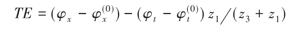
Where:
φ x、 φ T – rotation angle of planet carrier and sun gear;
φ (0)x 、 φ (0) T – initial rotation angle of planet carrier and sun gear.
The calculation of transmission error te of planetary gear train is mainly based on gear manufacturing error te (1), which is composed of single error of gear accuracy, such as cumulative pitch deviation FP and profile deviation F α Etc.) and gear contact deformation TE2, and its expression is as follows:
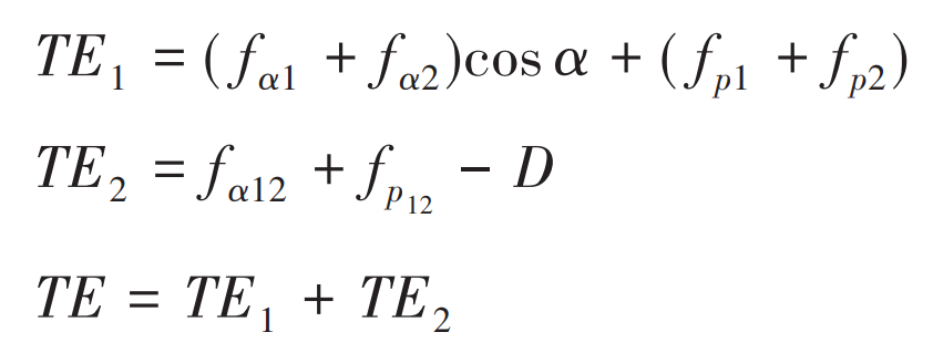
Where: D – tooth contact deformation.
(2) Meshing stiffness
If the meshing process of gear transmission is approximately regarded as an elastic change process, the contact stiffness of the gear changes continuously with the rotation of the gear, which will lead to the meshing impact between the teeth, and then cause the change of the dynamic response of the system, resulting in vibration and noise of the system. In order to reduce the gear noise essentially, the change of stiffness in the transmission process of gear pair should be as gentle as possible. Generally speaking, the gear normal meshing stiffness can be expressed by the following formula:
Where: FN δ N-normal contact force and normal comprehensive elastic deformation.
The relationship between normal meshing stiffness and tangential meshing stiffness is:
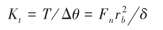
Where:
T – load torque of gear;
Δθ— Angle of gear;
FN – normal force of gear meshing point;
RB – radius of the base circle of the gear;
δ— The linear deformation of the gear pair along the meshing line.
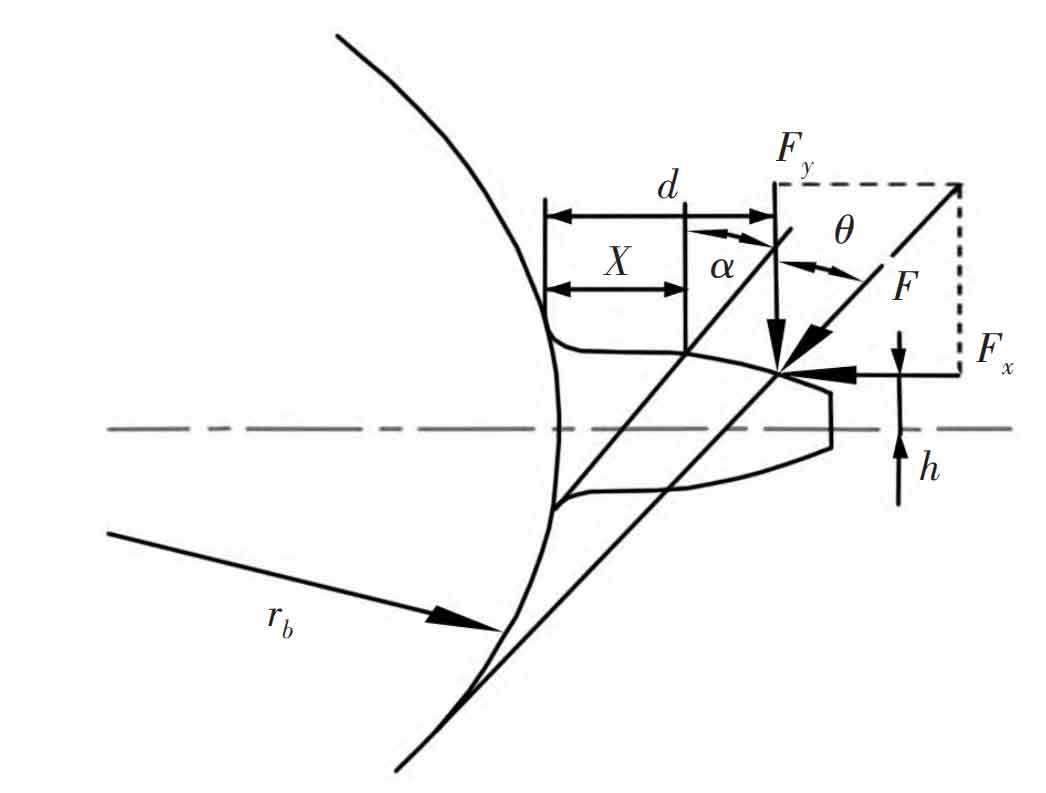
Here, according to Weber – banaschek method and hook formula, the comprehensive elastic deformation of the gear is divided into the deformation of the gear itself, the elastic deformation at the gear root, local contact deformation and Hertz deformation. Generally, under the action of meshing force, the deformation of gear is mainly composed of bending, shear and compression deformation. The cantilever beam model is used to simulate the deformation of gear, as shown in Figure 2. Here, the bending stiffness KB, shear stiffness KS and stiffness Ka caused by tooth root compression are obtained by energy method, which can be calculated by formula respectively. In addition, the Hertz deformation of the gear should be considered when calculating the tooth deformation, as shown in Figure 3. That is, the Hertz contact stiffness KH needs to be added when calculating the meshing stiffness of the system, which can be calculated by the formula.
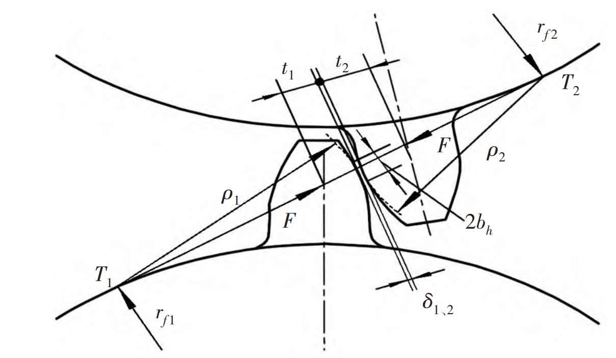
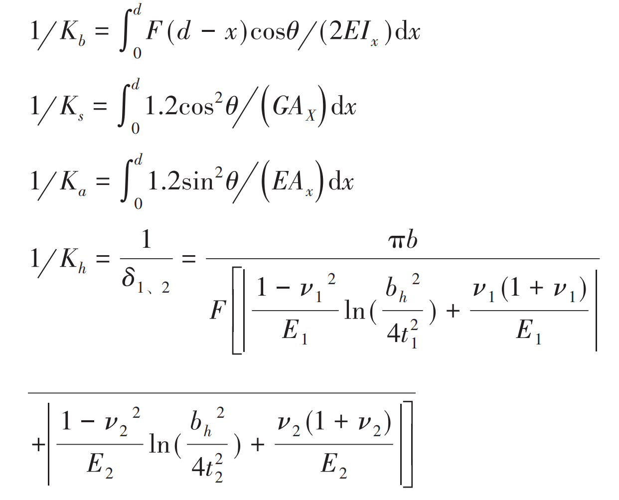
Where:
F – gear tooth surface load;
E and G – elastic modulus and shear modulus of gear;
IX, ax – moment of inertia and sectional area of the section x away from the fixed end of the gear;
θ— Meshing pressure angle of gear pair.
It can be concluded that the total meshing stiffness of a pair of teeth of sun gear and planetary gear is:
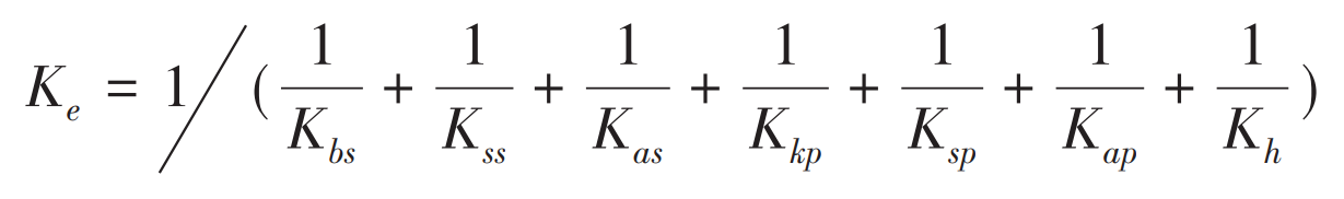
Where: subscript s – sun wheel; Subscript p – planetary gear.