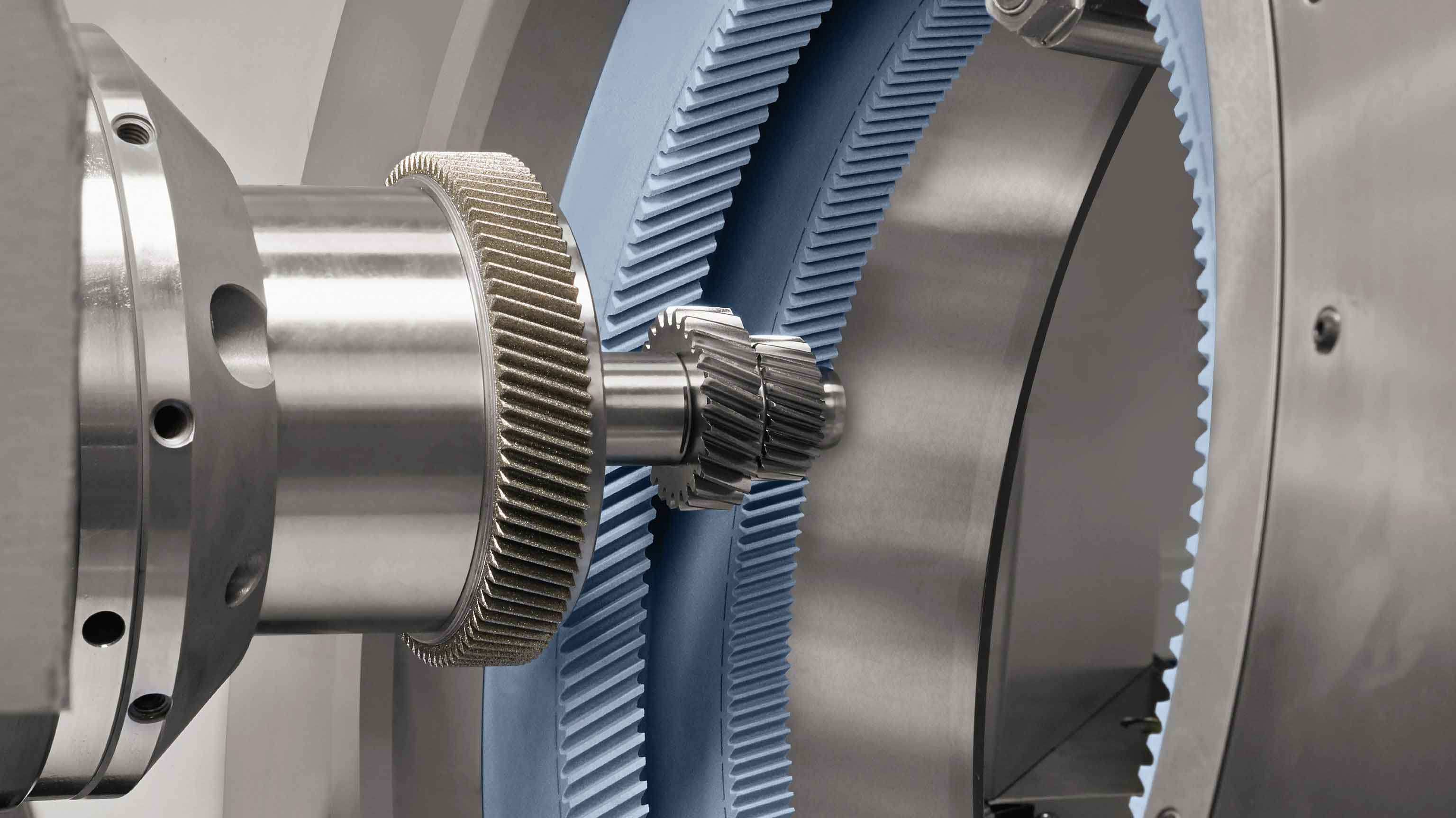
Internal gear power honing represents a critical advancement in gear finishing technology, delivering high precision and efficiency. The process involves an internal gear-shaped honing wheel engaging with a workpiece under crossed-axis conditions, where abrasive particles remove material through controlled relative motion. Maintaining consistent contact between the honing wheel and workpiece tooth surfaces is essential for geometric accuracy. However, traditional radial dressing methods introduce progressive deviations in workpiece tooth profiles due to altered contact conditions. We address this by developing a variable crossed-axis angle dressing methodology that preserves conjugate contact relationships.

The conjugate contact condition between the honing wheel (coordinate system $S_2$) and workpiece ($S_1$) is governed by the relative velocity and surface normal orthogonality. Defining fixed coordinate systems $S(Oxyz)$ and $S_p(O_px_py_pz_p)$ with center distance $a$ and crossed-axis angle $\Sigma$, the workpiece tooth surface is expressed parametrically. For a standard helical involute surface:
$$ \begin{align*}
x_1 &= r_b \cos(\sigma_0 + \theta + \lambda) + r_b \lambda \sin(\sigma_0 + \theta + \lambda) \\
y_1 &= r_b \sin(\sigma_0 + \theta + \lambda) – r_b \lambda \cos(\sigma_0 + \theta + \lambda) \\
z_1 &= \theta \cdot p
\end{align*} $$
where $r_b$ denotes base circle radius, $p = r_1 / \tan\beta_1$ is the lead, $\sigma_0$ is the involute start angle, $\theta$ is the helix increment angle, and $\lambda$ is the involute increment angle. The conjugate meshing equation satisfies $\mathbf{v} \cdot \mathbf{n} = 0$, yielding:
$$ (\theta p^2 – \lambda r_b^2) \sin\Sigma \sin(\phi_1 + \tau) + (a p \cos\Sigma – r_b^2 \sin\Sigma) \cos(\phi_1 + \tau) = r_b a \sin\Sigma – (\cos\Sigma – i_{12}) p r_b $$
where $\tau = \sigma_0 + \theta + \lambda$, $\phi_1$ is workpiece rotation, and $i_{12}$ is the transmission ratio. Contact lines at discrete $\phi_1$ angles reveal how single radial dressing disrupts stability. For a sample gear pair:
| Component | Parameter | Value |
|---|---|---|
| Common | Normal Module $m_n$ (mm) | 2.25 |
| Normal Pressure Angle $\alpha_n$ (°) | 17.5 | |
| Center Distance $a$ (mm) | 87.471 | |
| Workpiece | Teeth $z_1$ | 73 |
| Helix Angle $\beta_1$ (°) | 33 | |
| Face Width $b_1$ (mm) | 27 | |
| Honing Wheel | Teeth $z_2$ | 123 |
| Helix Angle $\beta_2$ (°) | 41.722 | |
| Face Width $b_2$ (mm) | 30 |
Radial dressing shifts contact lines toward the honing wheel’s root zone (Fig. 3). After 2mm cumulative dressing, the equivalent force position migrates 0.8mm axially, reducing material removal at the workpiece tooth root during gear honing. This manifests as progressive tooth profile deviations exceeding 15µm after five dressing cycles.
Our variable axis angle method preserves contact stability at a defined point $C$ on the workpiece tooth surface where $\phi_{1C} = 0°$ and $\theta_C = 0°$. Substituting $\lambda_C = 20.420°$ into the modified meshing equation maintains conjugacy:
$$ (\theta_C p^2 – \lambda_C r_b^2) \sin\Sigma’ \sin(\tau_C + \phi_{1C}) + (a’ p \cos\Sigma’ – r_b^2 \sin\Sigma’) \cos(\tau_C + \phi_{1C}) = r_b a’ \sin\Sigma’ – (\cos\Sigma’ – i_{12}) p r_b $$
where $a’ = a + \Delta a$ is the dressed center distance. The computational relationship between $\Delta a$ and $\Sigma’$ is:
| Radial Dressing $\Delta a$ (mm) | Adjusted Center Distance $a’$ (mm) | Corrected Axis Angle $\Sigma’$ (°) |
|---|---|---|
| 0.0 | 87.471 | 8.722 |
| 1.0 | 88.471 | 9.064 |
| 2.0 | 89.471 | 9.402 |
| 3.0 | 90.471 | 9.734 |
Simulation results demonstrate contact line coherence under variable axis angle dressing. At $\phi_1 = \{-3°, 0°, 3°\}$, contact lines for $\Delta a = 0-3$mm exhibit positional deviations below 0.05mm versus 0.8mm in radial dressing. The maximum equivalent force shift is contained within 0.1mm, ensuring stable pressure distribution during gear honing cycles.
Experimental validation employed a HMX-400 Fassler CNC gear honing machine and Klingelnberg P40 gear measuring center. Workpieces were processed using $\Delta a = 0.1$mm per dressing cycle with $\Sigma’$ adjustments per Table 2. Tooth profile evaluations across axis angles showed:
- Profile form error variation < 4µm across $\Sigma’ = 9°$ to $13°$
- No observable trend deviation in root/tooth curvature
- Surface roughness $R_a$ improved from 0.8µm to 0.5µm post-dressing
Implementing variable crossed-axis angle dressing extends honing wheel service life by 40% while maintaining tooth profile accuracy within ISO 1328 Class 6. The method’s computational efficiency enables real-time CNC compensation, making it suitable for high-volume precision gear honing applications requiring stable finishing performance.
