
In the realm of precision mechanical transmission, the rotary vector reducer stands as a pivotal component, renowned for its high torque capacity, compact design, and exceptional efficiency. As an engineer deeply involved in drive system design, I find that the proper selection of a rotary vector reducer is critical to ensuring system reliability, longevity, and performance. This article delves into a comprehensive methodology for choosing these reducers, focusing on load characteristics and main bearing power analysis. I will explore the structural principles, derive key performance equations, and provide detailed examples to guide practitioners through the selection process. Throughout this discussion, the term ‘rotary vector reducer’ will be frequently emphasized to underscore its central role in modern automation and robotics.
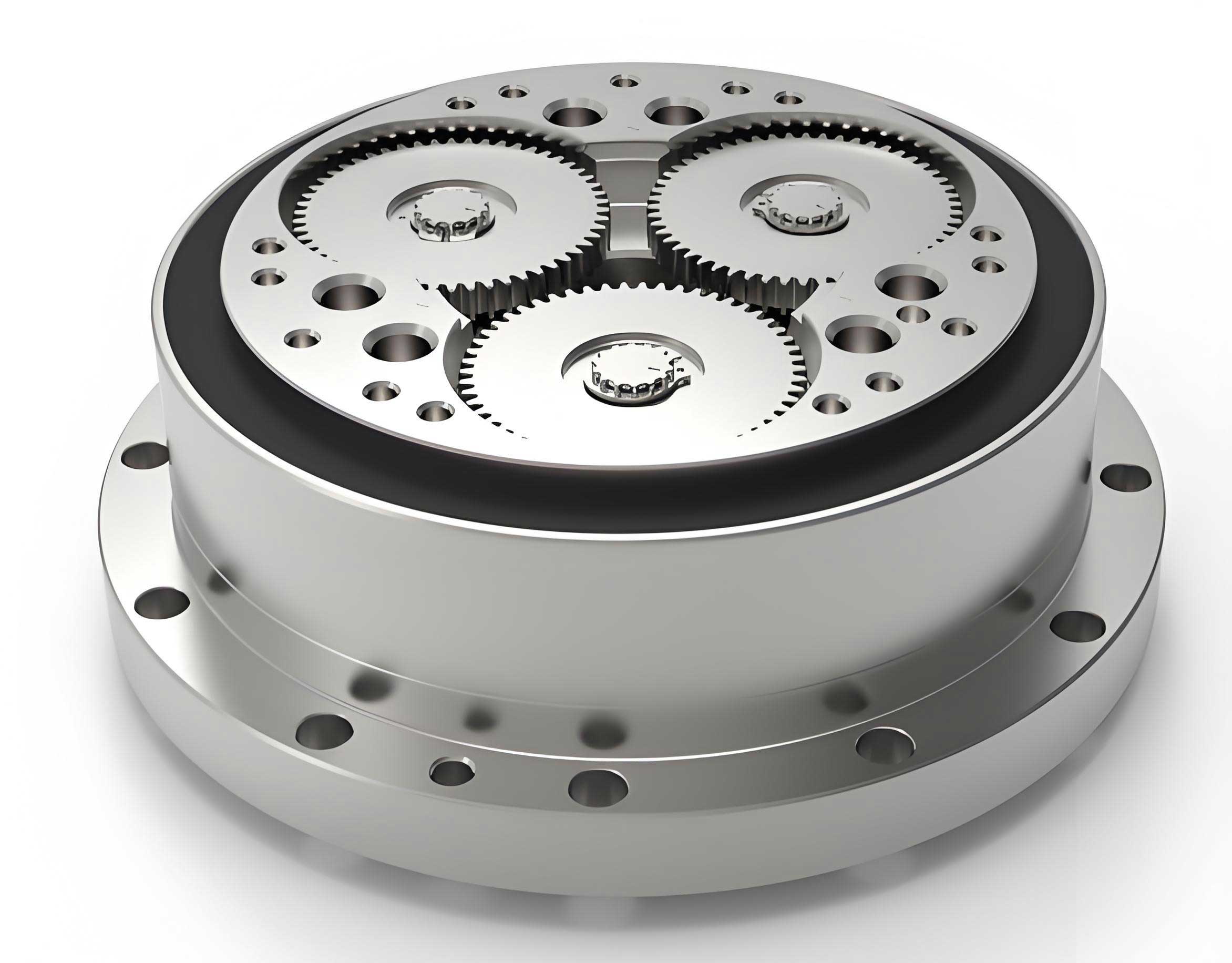
The rotary vector reducer, particularly the RV-C type, embodies an advanced evolution of cycloidal drive technology. Its architecture typically features a two-stage reduction system housed within a hollow shaft configuration, allowing for cable pass-through and space-saving integration. The first stage involves a conventional gear train, while the second employs a cycloidal pin-wheel mechanism that delivers high reduction ratios with minimal backlash. This design grants the rotary vector reducer superior attributes such as high torsional rigidity, excellent shock load absorption (often up to 500% of rated torque), and prolonged service life due to rolling contact dynamics. Understanding these inherent characteristics is the foundation for any selection procedure, as they directly influence how the reducer interacts with operational loads and environmental conditions.
To systematically select a rotary vector reducer, the process must bifurcate into two core analytical streams: the assessment of load characteristics and the evaluation of main bearing power capacity. Load characteristics encompass the dynamic torque and speed profiles the reducer experiences, while bearing power relates to its ability to withstand external radial and moment loads without excessive deflection or premature failure. The following table summarizes the primary performance indices that must be calculated during this dual-faceted analysis:
| Performance Index | Symbol | Description | Criticality in Selection |
|---|---|---|---|
| Average Load Torque | $$T_m$$ | Root mean cube value of varying torques over time | Determines preliminary size based on thermal and fatigue limits |
| Average Output Speed | $$N_m$$ | Time-weighted mean output rotational speed | Used in conjunction with $$T_m$$ for life estimation |
| Starting/Stopping Torque | $$T_{start}, T_{stop}$$ | Peak torque during acceleration and deceleration phases | Must not exceed the reducer’s allowable transient torque rating |
| Impact or Emergency Stop Torque | $$T_{em}$$ | Short-duration, high-magnitude torque from shocks or e-stops | Must be below the maximum instantaneous allowable torque |
| Moment Rigidity (Tilt Stiffness) | $$M_t$$ | Resistance to angular deflection under moment load | Ensures positional accuracy; calculated from bearing stiffness |
| Output Shaft Tilt Angle | $$\theta$$ | Angular deflection caused by external loads | Must be within permissible limits for the application |
| Load Moment on Bearing | $$M_c$$ | Resultant moment from offset forces on the output shaft | Must be less than the reducer’s rated moment capacity |
| Service Life (B10 Life) | $$L_h$$ | Expected operational hours before failure probability reaches 10% | Calculated based on $$T_m$$ and $$N_m$$; must meet design life |
The mathematical foundation for evaluating a rotary vector reducer’s load characteristics begins with the calculation of the equivalent average load torque. This is not a simple arithmetic mean but a root mean cube value that accounts for the cubic relationship between torque, stress, and fatigue life in gear teeth and bearings. For a load cycle consisting of ‘n’ segments, each with time $$t_i$$, output speed $$N_i$$, and load torque $$T_i$$, the average load torque $$T_m$$ is given by:
$$T_m = \sqrt[3]{\frac{\sum_{i=1}^{n} (t_i \cdot N_i \cdot T_i^{10/3})}{\sum_{i=1}^{n} (t_i \cdot N_i)}}$$
This formula, specific to the rotary vector reducer’s material and design, effectively condenses a variable load spectrum into a single constant torque value that produces equivalent fatigue damage. Simultaneously, the average output speed $$N_m$$ is computed as a time-weighted average:
$$N_m = \frac{\sum_{i=1}^{n} (t_i \cdot N_i)}{\sum_{i=1}^{n} t_i}$$
With $$T_m$$ and $$N_m$$ determined, one can consult the manufacturer’s rating tables for a preliminary selection of a rotary vector reducer model. The selected model’s rated torque $$T_0$$ and rated speed $$N_0$$ are then used to estimate its service life using the standardized life equation. For a rotary vector reducer, the calculated life $$L_h$$ in hours is:
$$L_h = L_{10} \cdot \left( \frac{N_0}{N_m} \right) \cdot \left( \frac{T_0}{T_m} \right)^{10/3}$$
Here, $$L_{10}$$ is the basic rated life in hours at the rated speed $$N_0$$ and rated torque $$T_0$$. This life calculation is paramount, as it directly informs whether the chosen rotary vector reducer will survive the application’s required lifespan without failure.
The second pillar of selection involves the main bearing system of the rotary vector reducer. These bearings support external loads from the driven machinery and must maintain shaft alignment and system rigidity. The key metrics are the moment rigidity $$M_t$$ and the resulting tilt angle $$\theta$$. The tilt angle, representing the angular deflection of the output shaft under a combination of radial loads, is calculated as follows for a common load case with two forces:
$$\theta = \frac{W_1 \cdot l_1 + W_2 \cdot l_3}{M_t \cdot 10^3}$$
In this equation, $$W_1$$ and $$W_2$$ are the external radial forces (in Newtons), $$l_1$$ and $$l_3$$ are their respective distances from the bearing face (in millimeters), and $$M_t$$ is the moment rigidity of the rotary vector reducer’s main bearing (in N·m/arc-min). The specification for the maximum allowable tilt angle (often in arc-minutes) is provided by the manufacturer and must not be exceeded to prevent binding, excessive wear, or seal damage. Furthermore, the total load moment $$M_c$$ applied to the bearing must be checked against the reducer’s rated moment capacity $$M_{rated}$$:
$$M_c = W_1 \cdot l_2 + W_2 \cdot l_1$$
where $$l_2$$ is the effective moment arm for force $$W_1$$, often extending from the bearing to the load point. The condition $$M_c < M_{rated}$$ must be strictly satisfied for a safe and reliable installation of the rotary vector reducer.
To solidify this theoretical framework, let’s embark on a detailed example calculation. Suppose I am designing a rotary indexing system for an assembly machine. The load profile, as determined from motion simulation, consists of three distinct phases per cycle. The parameters are meticulously defined in the following table:
| Phase | Description | Duration, $$t_i$$ (s) | Output Speed, $$N_i$$ (rpm) | Load Torque, $$T_i$$ (N·m) |
|---|---|---|---|---|
| 1 | Acceleration to position | 0.2 | 10 | 600 |
| 2 | Dwell and process | 0.5 | 20 | 150 |
| 3 | Deceleration to stop | 0.2 | 10 | 300 |
| Emergency Stop (Impact) | 0.05 | 20 | 1700 | |
Additionally, the external load conditions on the output shaft are: a radial force $$W_1 = 2500 \text{ N}$$ at a distance $$l_1 = 500 \text{ mm}$$, and a second force $$W_2 = 1000 \text{ N}$$ at $$l_2 = 200 \text{ mm}$$ from the mounting flange. The system requires a minimum life of 15,000 hours. My task is to select an appropriate rotary vector reducer.
First, I compute the average load torque $$T_m$$ and average speed $$N_m$$ for the main cycle (excluding the emergency stop for this initial calculation):
$$T_m = \sqrt[3]{\frac{(0.2 \cdot 10 \cdot 600^{10/3}) + (0.5 \cdot 20 \cdot 150^{10/3}) + (0.2 \cdot 10 \cdot 300^{10/3})}{(0.2 \cdot 10) + (0.5 \cdot 20) + (0.2 \cdot 10)}}$$
$$T_m = \sqrt[3]{\frac{0.2 \cdot 10 \cdot (600^{3.333}) + 0.5 \cdot 20 \cdot (150^{3.333}) + 0.2 \cdot 10 \cdot (300^{3.333})}{2 + 10 + 2}} \approx 348.9 \text{ N·m}$$
$$N_m = \frac{(0.2 \cdot 10) + (0.5 \cdot 20) + (0.2 \cdot 10)}{0.2 + 0.5 + 0.2} = \frac{2 + 10 + 2}{0.9} \approx 15.6 \text{ rpm}$$
Consulting a catalog for rotary vector reducers, a model with a rated torque $$T_0 = 490 \text{ N·m}$$ and a rated speed $$N_0 = 15 \text{ rpm}$$ emerges as a candidate (let’s denote it as size RV-50C). I now verify its projected life:
$$L_h = 6000 \cdot \left( \frac{15}{15.6} \right) \cdot \left( \frac{490}{348.9} \right)^{10/3}$$
$$L_h \approx 6000 \cdot 0.9615 \cdot (1.404)^{3.333} \approx 6000 \cdot 0.9615 \cdot 2.985 \approx 17,250 \text{ hours}$$
This exceeds the required 15,000 hours, satisfying the life criterion. Next, I check the dynamic torque limits. The maximum speed during operation (20 rpm) is checked against the reducer’s maximum allowable speed (say, 50 rpm for this model)—this condition is met. The starting and stopping torques (600 N·m and 300 N·m) are compared to the model’s allowable start/stop torque (say, 1225 N·m)—both are safe. The emergency stop impact torque of 1700 N·m is compared to the instantaneous maximum allowable torque (say, 2450 N·m), which is also acceptable.
Now, I shift focus to the main bearing power analysis for this rotary vector reducer. The moment rigidity $$M_t$$ for the candidate model is specified as 1960 N·m/arc-min. I calculate the expected tilt angle $$\theta$$:
$$\theta = \frac{2500 \cdot 500 + 1000 \cdot 200}{1960 \cdot 10^3} = \frac{1,250,000 + 200,000}{1,960,000} = \frac{1,450,000}{1,960,000} \approx 0.74 \text{ arc-minutes}$$
If the manufacturer’s specification allows a tilt angle of, for example, 1.0 arc-minutes, this condition is satisfied. Finally, I compute the total load moment $$M_c$$. First, I determine the effective distance $$l_2$$ for force $$W_1$$, which is the distance from the bearing’s center to the load point: $$l_2 = 500 \text{ mm} + \text{(half the shaft length, say 94 mm)} = 594 \text{ mm} = 0.594 \text{ m}$$.
$$M_c = 2500 \cdot 0.594 + 1000 \cdot 0.200 = 1485 + 200 = 1685 \text{ N·m}$$
This value is compared to the reducer’s rated moment capacity (say, 1764 N·m). Since 1685 N·m < 1764 N·m, the condition is met. All criteria from both load characteristics and main bearing power analyses are satisfied, confirming that the RV-50C rotary vector reducer is a suitable and robust choice for this application.
Beyond the core selection methodology, several ancillary factors warrant consideration when integrating a rotary vector reducer. Lubrication is critical; most units are filled with lifelong grease, but operating temperature ranges must be respected to maintain viscosity and prevent leakage. Backlash, though inherently low in a rotary vector reducer due to its preloaded cycloidal design, should still be specified according to the precision needs of the application, such as in robotic arms or CNC rotary tables. Mounting configuration—whether flange, shaft, or foot-mounted—affects the load distribution on the housing and must be aligned with the machine frame’s stiffness. Furthermore, the hollow shaft feature of many rotary vector reducers offers immense practicality for routing cables, hydraulic lines, or laser paths, but the bore size and keyway specifications must be matched to the driven shaft.
The advantages of a rotary vector reducer extend into comparative performance metrics. When evaluated against traditional planetary gear reducers or harmonic drives, the rotary vector reducer typically exhibits a superior torque-to-volume ratio, higher overload capacity, and better stiffness. The following table provides a qualitative comparison based on key application-driven parameters:
| Performance Parameter | Rotary Vector Reducer | Planetary Gear Reducer | Harmonic Drive Reducer |
|---|---|---|---|
| Single-Stage Reduction Ratio Range | 30:1 to 200:1 | 3:1 to 12:1 | 50:1 to 160:1 |
| Torsional Rigidity | Very High | High | Moderate to High |
| Overload Capacity (% of Rated Torque) | Up to 500% | 200-300% | 200-400% |
| Backlash | Low (< 1 arc-min typical) | Medium (3-10 arc-min) | Very Low (< 0.5 arc-min) |
| Efficiency at Full Load | > 90% | > 95% | 80-90% |
| Shock Load Tolerance | Excellent | Good | Fair to Good |
| Hollow Shaft Availability | Standard | Common Option | Standard |
Maintenance philosophy for a rotary vector reducer is generally “fit and forget” for the sealed, grease-lubricated units. However, monitoring operational temperature and vibration levels can provide early warnings of potential issues like bearing wear or seal failure. In high-cycle or continuous duty applications, a preventive maintenance schedule might include periodic re-greasing, but this is often specified for extreme conditions only. The robust construction of a rotary vector reducer contributes directly to its long service intervals.
In conclusion, the systematic selection of a rotary vector reducer, as I have detailed, is a non-negotiable discipline for achieving optimal performance in demanding mechanical systems. The dual-path analysis—scrutinizing the time-varying load profile to derive equivalent average torque and speed, and then verifying the main bearing’s capacity against external forces and moments—forms a rigorous, reliable procedure. The mathematical tools, from the root mean cube torque formula to the life equation and rigidity calculations, empower engineers to make data-driven decisions. The worked example illustrates the practical application of these principles, ensuring that the chosen rotary vector reducer meets all life, torque, speed, and rigidity requirements. As motion systems grow more complex and performance expectations rise, the role of the correctly specified rotary vector reducer becomes ever more critical in bridging the gap between motor output and precise, reliable mechanical work.