
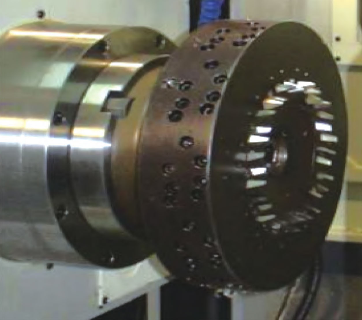
The quasi hyperboloid gear hob is shown in Figure 1. Its tool set is composed of several strip blades. A tool set can have up to three kinds of blades, namely, internal blade, middle blade and external blade. Sometimes, middle blade is not required. The middle cutter is mostly used for rough cutting, the inner cutter is used for cutting the convex surface of gears, and the outer cutter is used for cutting the concave surface of gears. When machining left-hand gears, use a left-hand cutter head for cutting; When machining right-hand gears, use right-hand cutting tools for cutting. Due to the main purpose of the article being to establish a mathematical model of the tooth surface, the establishment of the tool mathematical equation does not consider the case of rough cutting.
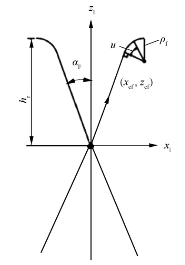
The edge lines of surface rolling cutters are divided into straight edges and rounded edges, as shown in Figure 2.
According to the cutterhead coordinate system in Figure 3, the cutterhead line equation rl (u) located in the cutterhead coordinate system Sl is converted to the cutterhead coordinate system St to obtain the position vector of the cutterhead line located in the cutterhead coordinate system. When the aforementioned symbol is used in Figure 3 to represent the coordinate system, I and A are added to the subscript to correspond to the inner and outer knives, respectively.
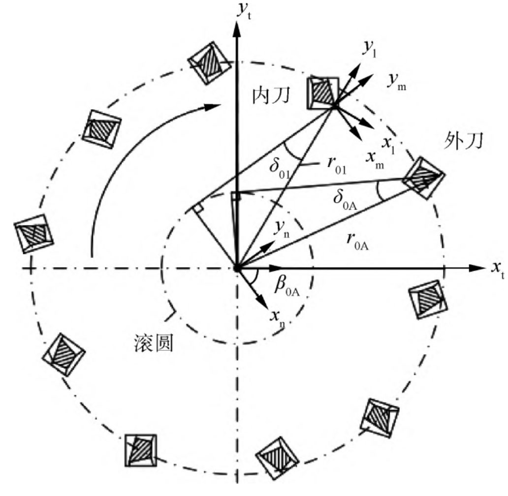
In Figure 3, xt and yt respectively represent the horizontal and vertical axes of the cutter head coordinate system; Xn, yn represents deflection along the cutter head coordinate system β The new coordinate system obtained from the initial angle of 0; Xl, yl represent the tangential coordinates of the tool edge line; Xm and ym represent the normal coordinates of the tool edge line.