
1. Introduction to Hypoid Gear
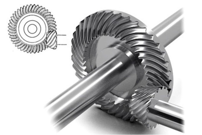
Hypoid gear, a specialized type of bevel gears, are widely recognized for their unique offset configuration between the pinion and gear axes. This offset, typically ranging from 20–50 mm in automotive applications, enhances load-bearing capacity, transmission efficiency, and noise reduction. Unlike spiral bevel gears, hypoid gear exhibit sliding motion in both the tooth height and length directions, which facilitates smoother meshing, improved contact patterns, and post-heat-treatment grinding compatibility. These advantages make hypoid gear indispensable in automotive differential systems, heavy machinery, and aerospace applications.
Despite their superior performance, the manufacturing of hypoid gear remains challenging due to their complex geometry and stringent precision requirements. Traditional cradle-type gear-cutting machines rely on mechanical adjustments that limit flexibility and accuracy. Modern six-axis CNC machines offer greater control but require advanced mathematical models to translate legacy machine settings into programmable coordinates. This paper addresses this gap by proposing a robust mathematical framework for hobbing hypoid gear using the Spiroflex method, validated through simulations and experimental data.
2. Mathematical Model Development
2.1 Coordinate System Transformation
The foundation of the model lies in converting the coordinate system of universal cradle-type machines to align with six-axis CNC machines. Key coordinate frames include:
- Tool coordinate system (S₁): Defines the position of cutting blades.
- Generated gear coordinate system (S₂): Represents the virtual generating gear.
- Workpiece coordinate system (S₃): Describes the hypoid gear being machined.
The transformation matrices between these systems account for tool rotation angles, machine tilt parameters, and offset adjustments. For instance, the tool edge equation in S₁ is expressed as:r(u)=[x1(u)0z1(u)1]Tr(u)=[x1(u)0z1(u)1]T
where x1(u)x1(u) and z1(u)z1(u) are derived from blade geometry parameters such as rake angle (αtαt), fillet radius (ρaρa), and reference height (htht).
2.2 Tool Geometry and Cutting Edge Equations
Hypoid gear hobbing employs face-milling cutters with inner, middle, and outer blades. The cutting edge comprises a straight segment and a fillet, modeled as:
- Fillet segment (r1(0)(u)r1(0)(u)):
{x1(0)(αt,u)=usinαtz1(0)(αt,u)=ucosαt{x1(0)(αt,u)=usinαtz1(0)(αt,u)=ucosαt
- Straight segment (r1(1)(u)r1(1)(u)):
{x1(1)(αt,ρa,ht,u)=±(xd−ρacosu)z1(1)(αt,ρa,ht,u)=zd+ρasinu{x1(1)(αt,ρa,ht,u)=±(xd−ρacosu)z1(1)(αt,ρa,ht,u)=zd+ρasinu
Here, xdxd and zdzd denote the fillet center coordinates, and the ± sign corresponds to inner/outer blades.
2.3 Tooth Surface Generation
The tooth surface is derived by transforming the cutting edge trajectory from S₁ to S₃ via intermediate frames. The generating gear (S₂) acts as a virtual tool, simulating the relative motion between the cutter and workpiece. The transformation chain is:rw(u,β,φc)=MwgMgdMdcMcbr1(u)rw(u,β,φc)=MwgMgdMdcMcbr1(u)
where ββ, φcφc, and φ1φ1 represent tool rotation, cradle angle, and workpiece rotation, respectively. The matrices MM encapsulate rotational and translational adjustments.
The meshing condition ensures continuous contact between the tool and workpiece:nw(u,β,φc)⋅vw(12)(u,β,φc)=0nw(u,β,φc)⋅vw(12)(u,β,φc)=0
Here, nwnw is the surface normal vector, and vw(12)vw(12) is the relative velocity.
3. Six-Axis CNC Machine Setup
3.1 Machine Configuration
The six-axis CNC hypoid gear generator features vertical tool/workpiece spindles with programmable axes:
- Tool axes: Radial (cycy), vertical (cxcx), and tilt (ΨaΨa).
- Workpiece axes: Tilt (ΨbΨb), rotation (ΨcΨc), and offset (ΔA,ΔBΔA,ΔB).
The coordinate transformation matrix MwtMwt ensures equivalence between cradle-type and CNC machines:Mwt=MwbMbcMcdMdtMtaMwt=MwbMbcMcdMdtMta
Key parameters include:
- ΨaΨa: Tool tilt angle.
- ΔΨbΔΨb: Workpiece tilt increment.
- MdMd: Workpiece mounting distance.
3.2 Parameter Conversion
Cradle machine settings are converted to CNC axes using displacement equations:{cx=−a14cosΨc−a24sinΔΨbsinΨc−a34cosΔΨbsinΨc−Hf+kxcosΨc−kzsinΨccy=sinΨc(−a14+a24sinΔΨbcotΨc+a34cosΔΨbcotΨc+Hf+kx)cz=a24cosΔΨb−a34sinΔΨb⎩⎨⎧cx=−a14cosΨc−a24sinΔΨbsinΨc−a34cosΔΨbsinΨc−Hf+kxcosΨc−kzsinΨccy=sinΨc(−a14+a24sinΔΨbcotΨc+a34cosΔΨbcotΨc+Hf+kx)cz=a24cosΔΨb−a34sinΔΨb
These equations ensure precise alignment of tool and workpiece positions.
4. Experimental Verification
4.1 Parameter Tables
Key parameters for hypoid gear machining are summarized below:
Table 1: Hypoid Gear Basic Parameters
| Parameter | Pinion (Convex) | Gear (Concave) |
|---|---|---|
| Number of Teeth (z) | 10 | 41 |
| Normal Module (mₙ) | 3.33 mm | 3.33 mm |
| Spiral Angle (βₘ) | 50.01° | 37.13° |
| Pressure Angle (α) | 22.13° | -17.87° |
| Offset (E) | 20 mm | 20 mm |
Table 2: Tool Parameters
| Parameter | Pinion (Convex) | Gear (Concave) |
|---|---|---|
| Blade Group (z₀) | 13 | 13 |
| Reference Height (hₜ) | 3.99 mm | 3.92 mm |
| Profile Angle (αₜ) | 20.90° | 23.70° |
| Direction Angle (δ₀) | 14.36° | -14.35° |
Table 3: Machine Settings
| Parameter | Pinion (Convex) | Gear (Concave) |
|---|---|---|
| Tilt Angle (Ψₐ) | 2° | 2° |
| Cradle Radius (Sᵣ) | 96.16 mm | 96.15 mm |
| Vertical Offset (Eₘ) | 17.75 mm | 2.16 mm |
| Horizontal Offset (ΔA) | 1.59 mm | -3.30 mm |
4.2 Error Analysis
The VERICUT simulation compared theoretical and machined hypoid gear:
- Tooth thickness error: +3.8 μm (pinion), -39.62 μm (gear).
- Surface position error: <30 μm for both gears.
These results confirm the model’s accuracy, with all errors below the 50 μm threshold.
5. Conclusion
This study presents a comprehensive mathematical model for hobbing hypoid gear using the Spiroflex method on six-axis CNC machines. By transforming cradle-type machine settings into CNC-compatible coordinates, the model achieves sub-50 μm accuracy in tooth geometry. Future work will focus on real-time adaptive control and multi-axis synchronization to further enhance hypoid gear manufacturing precision.