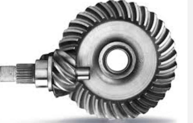
This paper presents a comprehensive mathematical framework for hypoid gear generation using the Spiroflex method on 6-axis CNC gear cutting machines. The model bridges traditional cradle-type machine settings with modern Cartesian coordinate systems through kinematic transformations, enabling precise tooth surface generation.

1. Coordinate System Transformation
The mathematical foundation starts with coordinate transformations between traditional cradle-type machines and modern 6-axis CNC systems. The transformation matrix for hypoid gear generation can be expressed as:
$$ M_{lt} = M_{ll’}M_{l’d}M_{dc}M_{cb}M_{ba}M_{at’}M_{t’t} $$
Key parameters in the transformation include:
| Parameter | Description |
|---|---|
| Ψb | Workpiece rotation axis tilt angle |
| ΔΨa | Cutter rotation axis angular increment |
| Em | Vertical offset |
| γm | Machine root angle |
2. Cutting Tool Geometry
The face-hobbed cutter geometry is defined by two distinct edge segments:
Straight edge:
$$ x_l^{(l)}(\alpha_F;u) = \pm u\sin\alpha_F $$
$$ z_l^{(l)}(\alpha_F;u) = u\cos\alpha_F $$
Fillet edge:
$$ x_l^{(f)}(\alpha_F,\rho_o,h_r;u) = \pm(x_{cf} – \rho_o\cos u) $$
$$ z_l^{(f)}(\alpha_F,\rho_o,h_r;u) = z_{cf} + \rho_o\sin u $$
| Parameter | Pinion | Gear |
|---|---|---|
| Blade groups (z0) | 13 | 13 |
| Reference height (hr) | 3.99-3.88 mm | 4.05-3.92 mm |
| Pressure angle (αF) | 20.9°-19.09° | 16.3°-23.7° |
3. Tooth Surface Generation
The meshing equation for hypoid gear tooth surfaces is derived as:
$$ f_1(u,\beta,\phi_c) = n_1(u,\beta,\phi_c) \cdot v_1^{(lt)}(u,\beta,\phi_c) = 0 $$
Where the normal vector and relative velocity are calculated through partial derivatives:
$$ n_1 = \frac{\partial r_1}{\partial u} \times \frac{\partial r_1}{\partial\beta} $$
$$ v_1^{(lt)} = \frac{\partial r_1}{\partial\phi_c}\dot{\phi}_c $$
4. Machine Settings Conversion
The critical angular relationships for 6-axis CNC machines are:
$$ \Psi_c = \pm\arccos(a_{13}) $$
$$ \Delta\Psi_a = \arctan\left(\frac{\pm a_{12}}{\pm a_{11}}\right) $$
$$ \Delta\Psi_b = \arctan\left(\frac{\pm a_{23}}{\pm a_{33}}\right) $$
| Parameter | Pinion | Gear |
|---|---|---|
| Workpiece tilt (Ψc) | 16.43° | 71.30° |
| Cutter offset (cx) | -0.48 mm | -0.17 mm |
| Vertical alignment (cz) | 1.59 mm | -3.30 mm |
5. Verification and Error Analysis
The mathematical model was validated through VERICUT simulation, showing excellent agreement with theoretical hypoid gear geometry:
$$ \Delta t_{pinion} = +3.8\mu m $$
$$ \Delta t_{gear} = -39.62\mu m $$
Tooth surface position errors remained below 50μm across all measured points, demonstrating the model’s effectiveness in hypoid gear manufacturing.
6. Computational Implementation
The complete coordinate transformation matrix for hypoid gear generation combines seven transformation components:
$$ M_{lt} = \begin{bmatrix}
\cos\Psi_b\cos\Delta\Psi_b & -\sin\Delta\Psi_b & \sin\Psi_b\cos\Delta\Psi_b & T_x \\
\cos\Psi_b\sin\Delta\Psi_b & \cos\Delta\Psi_b & \sin\Psi_b\sin\Delta\Psi_b & T_y \\
-\sin\Psi_b & 0 & \cos\Psi_b & T_z \\
0 & 0 & 0 & 1
\end{bmatrix} $$
Where translation components are calculated as:
$$ T_x = (M_d + H_f + k_x)\cos\Psi_c – k_z\sin\Psi_c $$
$$ T_y = E_m + c_z $$
$$ T_z = -(M_d + H_f + k_x)\sin\Psi_c – k_z\cos\Psi_c $$
This mathematical framework enables precise hypoid gear manufacturing on modern CNC machines while maintaining compatibility with traditional cradle-type machine settings.
