Theoretical circular arc tooth profile circular arc tooth line gear tooth surface can be generated by the circular arc tooth profile moving along the circular arc tooth line, but this tooth surface can only be milled by ball end milling cutter on multi axis CNC machine tool, which is high cost and low efficiency. According to the meshing principle of circular arc gear, the tooth surface of circular arc tooth profile circular arc tooth line gear can also be machined on the CNC milling machine of circular arc bevel gear with milling cutter head. This method has high machining efficiency and low cost. Firstly, according to the machining principle of spiral bevel gear milling machine, the mathematical model of circular arc tooth profile circular arc tooth profile cylindrical gear tooth surface is established.
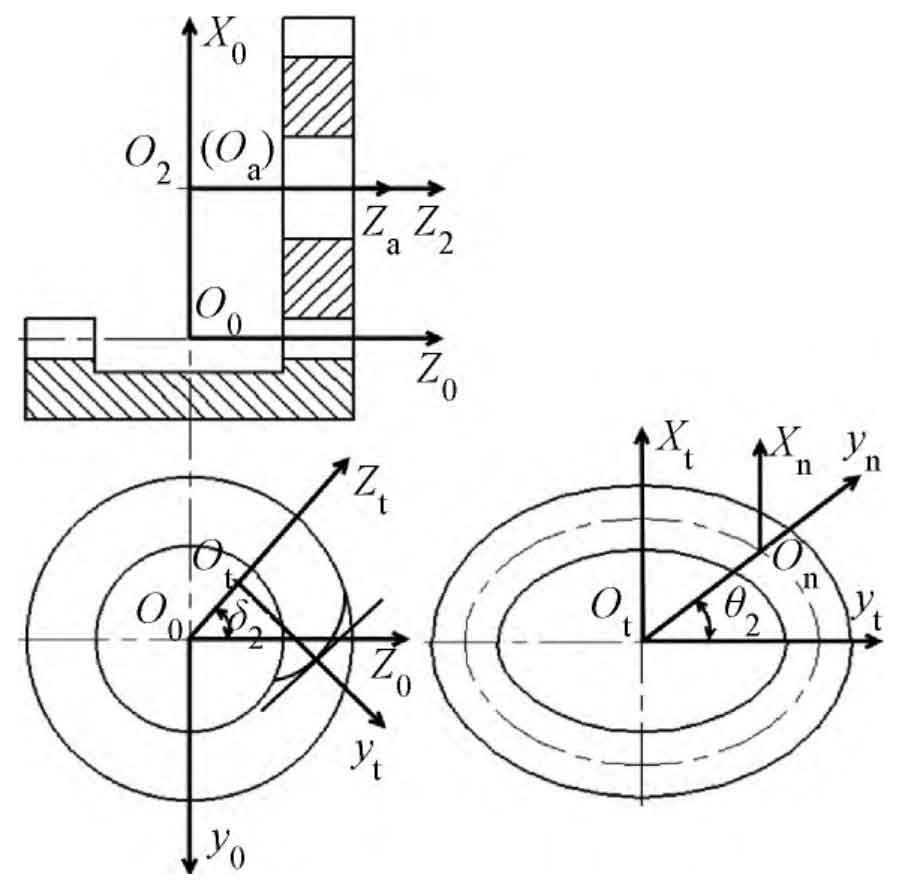
Establish the gear processing coordinate system, as shown in the figure. Among them, σ 0 = [o0-x0y0z0] is a coordinate system fixedly connected with the imaginary plane gear; σ T = [ot xtytzt] is a coordinate system fixedly connected with the milling cutter head; σ N = [on xnynzn] is a coordinate system fixed with the tooth profile of the milling cutter head; σ A = [OA xayaza] is the auxiliary coordinate system. σ 2 = [o2-x2y2z2] is the coordinate system fixed with the gear blank. The coordinate origin and coordinate axis direction of each coordinate system are shown in the figure.
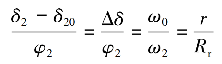
When machining gears, the assumed angular speed of plane gears is ω 0, the angular velocity of the gear blank is ω 2。 δ 20 is the initial tool position angle, δ 2 is the current tool position angle, φ 2 is the gear blank angle, the pitch radius of the gear is r, and the radius of the milling cutter head is RR, then R ω 2 =Rr ω 0, so: