
Ollicon hypoid gear processing machine tool (as shown in figure (a)) is mainly composed of cutting cutter head, cutter tilt device, cutter rotation device, shaking table, bed device, vertical wheel position device and horizontal wheel position device. The main parameters of the machine tool coordinate system include tool inclination, tool angle, radial tool position, angular tool position, roll ratio, bed position, vertical wheel position and horizontal wheel position. In the machine tool coordinate system, the coordinate systems st (XT, YT, ZT), Sj (XJ, YJ, ZJ) and SP (XP, YP, ZP) are fixed on the cutter head, machine tool and processing blank respectively. Formula through the coordinate transformation from St (XT, YT, ZT) to Sj (XJ, YJ, ZJ) (as shown in figure (b)), the rotary cutting surface of the tool is converted to the coordinate system of the machine tool, and the tooth surface equation of the virtual forming wheel is obtained; Through the coordinate transformation from Sj (XJ, YJ, ZJ) to sp (XP, YP, ZP) (as shown in figure (c)), the cutting path surface of the tool under the blank coordinate system is obtained, and the expression is as follows:
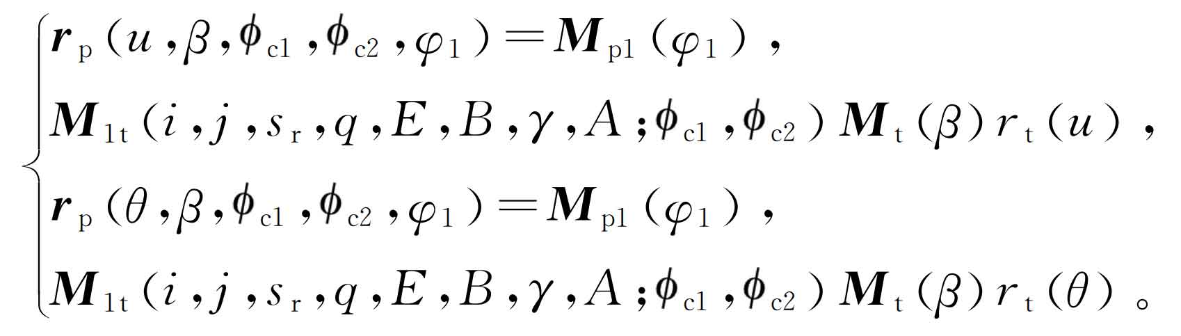
Where: m1t is the coordinate transformation of the machine tool; MP1 is the blank rotation coordinate system; MT is the cutter head rotation coordinate system. β Is the rotation angle of the cutter head, C1 and C2 are the incremental angle of the shaking table. The formula is a statically indeterminate equation, which needs to be solved by reducing the amount of solution according to the tooth surface forming method of hypoid gear.

In the forming process, the shaking table is fixed, and the incremental angle of the shaking table is zero, that is, C1 = 0 and C2 = 0; In generating method processing, the incremental angle of the shaking table changes with time, and the expressions of the incremental angles C1 and C2 of the shaking table are:
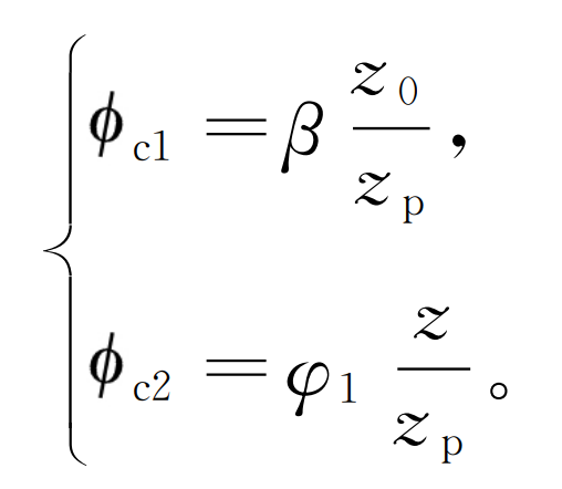
Where: Z, Z0 and ZP respectively represent the number of teeth of the hypoid gear blank, the number of tool heads and the number of profiled teeth; C1 is used to form an extended epicycloid, and C2 is used for tooth surface generation of hypoid gears.