Establish the coordinate system as shown in the figure according to the geometric model of the machine tool. Among them, the coordinate system S0 (O0murx0dynez0) is a static coordinate system established on the machine bed. The Z0 axis is parallel to the horizontal guide rail of the headbox, the Y0 axis is parallel to the vertical guideway on the headbox and is positive upward, and the x0 axis points to the direction of the worktable. Coordinate system S1 is the coordinate system established on the headbox of the machine tool. The x1 axis is parallel to x0 and the direction is opposite. The y1 axis coincides with the Z0 axis and has the same direction. The distance between the origin O1 and S0 of the coordinate system S1 (O1ripx1, Y1, Z1) and S0 (O0Murx0, Y0, Y0, Z0) is the distance between O0, the origin of the coordinate system, and O0, the origin of the coordinate system, O1, and S0, which is located on the headbox of the machine tool. The coordinate system S2 is built on the spindle box. The x2 axis is parallel to and opposite to Z0, the Y2 axis coincides with the Z1 axis, and the distance between the origin O2 and O1 is O1O2=L2. The coordinate system S3 is fixed on the cutter head and can rotate around the axis Z2. The axis Z3 coincides with the axis Z2. The distance between the origin O3 and O2 is that the angle between the axis x3 and the axis x2 is θ 1 on the projection plane (O2murx2Magny2). The coordinate system S3 is fixed on the cutter head and can rotate around the axis z2, and the axis Z3 coincides with the axis Z2. The distance between the origin O3 and O2 is the angle between the x3 axis and the x2 axis on the projection plane. The cutter head rotates around the Z2 axis at a uniform angular velocity ω 1. The cutter head axis moves along the Z1 axis at the speed v 2 and along the Z0 axis at the speed v 1 in the plane (O0murx0 ~ Y0). It is stipulated that the positive directions of ω 1, v 2 and v 1 are the same as those of z 2, z 1 and z 0, respectively.

Coordinate system 1 (coordinate 1) is a coordinate system established on the horizontal slide plate of machine tool worktable, in which the axis of y is coincident with the axis of x 0 and the direction is the same, the axis of z is parallel to y 0 and the direction is the same, and the distance between origin and O 0 is O0O’1=L3. The coordinate system Song2 is established on the turntable of the worktable and can rotate around the zonal axis. The axis of the axis coincides with the axis of the zonal 1 and is in the same direction. The distance between the origin of the axis and the origin of the axis is the angle between the projection of the axis and x1 on the plane (the angle between the projection of the axis and the axis of the plane, the angle between the projection of the axis and the axis of the axis) and the axis of the plane (the angle between the projection of the axis and the axis of the axis) and the plane (the angle between the projection of the axis and the axis of the axis) is θ A, and the angle between the projection of the axis and the axis of the axis is θ A. The coordinate system Send3 (obsolete 3 color 3) is firmly connected with the workpiece gear G, and the zonal 3 axis coincides with the zonal 2 axis. The angle between the projection of the x ray 3 axis and the x circle 2 on the plane is θ g, and the distance between the origin 3 and the object 2 is O’2O’3=S6, and the angle between the projection of the x axis 3 and the x ray 2 is θ g, and the distance between the origin and the gear 2 is the same. The gear rotates around the zonal 2 axis at an angular velocity ω g, and specifies that the positive direction of ω g is the same as that of zonal 2, respectively.
The axes of the above coordinate systems conform to the right-hand rule. In order to express conveniently, the coordinate components of the x, y and z axes of each coordinate system are represented by I, j and k respectively, and the footmarks are the same as those of each coordinate axis.
This paper first analyzes the processing situation of using left-handed production wheel to process right-hand wheel. Following is the derivation of the coordinate relationship between the point T on the cutterhead cutting edge (x1) and the point G (xg,yg,zg) on the working tooth surface meshing with it.
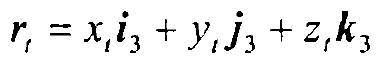
Let the vector of T point be expressed as rt in the cutter head coordinate system.
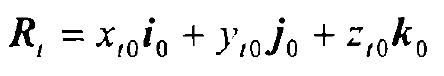
The vector in the static coordinate system S0 (O0murx0magnetic y0Powerz0) is expressed as Rt:
The transformation relationship between Rt and rt is as follows:
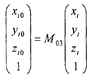
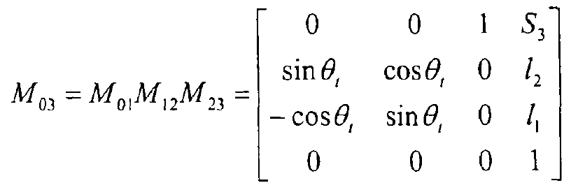
The transformation matrix M03 is derived from the following transformation relationship:
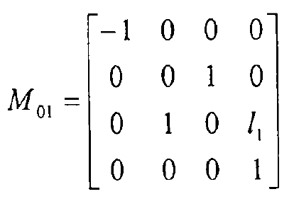
The transformation relationship between coordinate system S0 and S1:
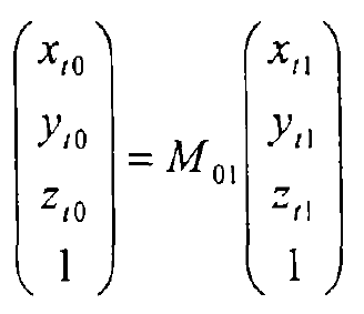
Among them.
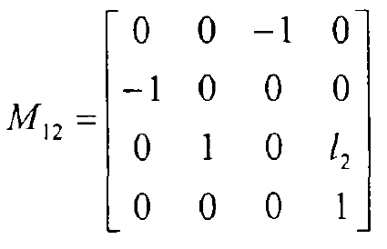
The transformation relationship between coordinate system S1 and S2:
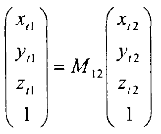
Among them.
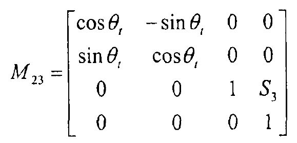
The transformation relationship between coordinate system S2 and S3:
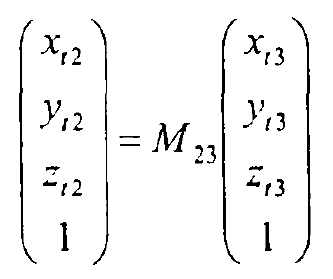
Among them.
From this.