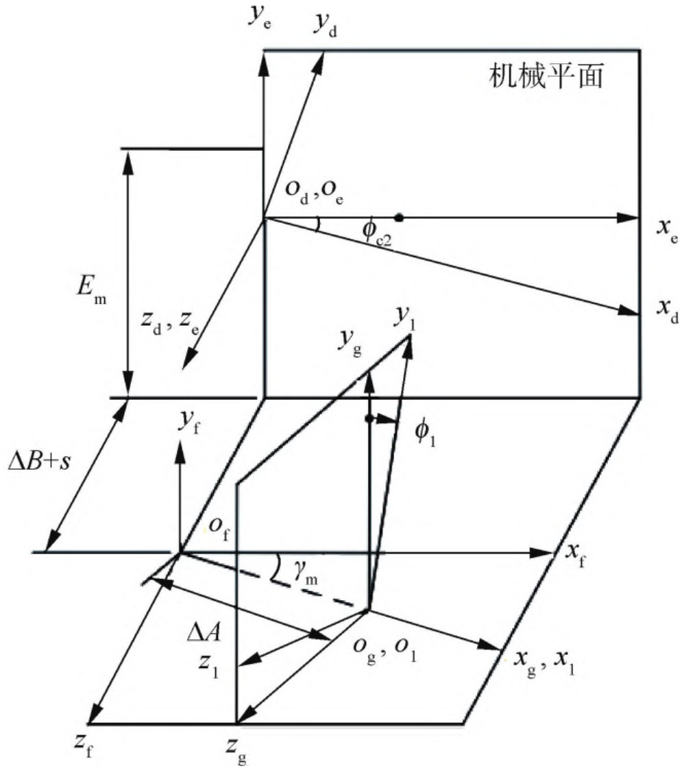
According to the mechanical setting of the calculation surface rolling quasi hyperboloid gear cutting machine. Figures 1 and 2 describe the position of the cutter head, the imaginary generating wheel and the workpiece roll quasi hyperboloid gear in the coordinate system of the universal rocker machine tool, where the coordinate system St is fixed to the cutter, the coordinate system Sd is fixed to the imaginary generating wheel, and the coordinate system Sl is fixed to the workpiece roll quasi hyperboloid gear. In Figure 1, SR is the tool radius.
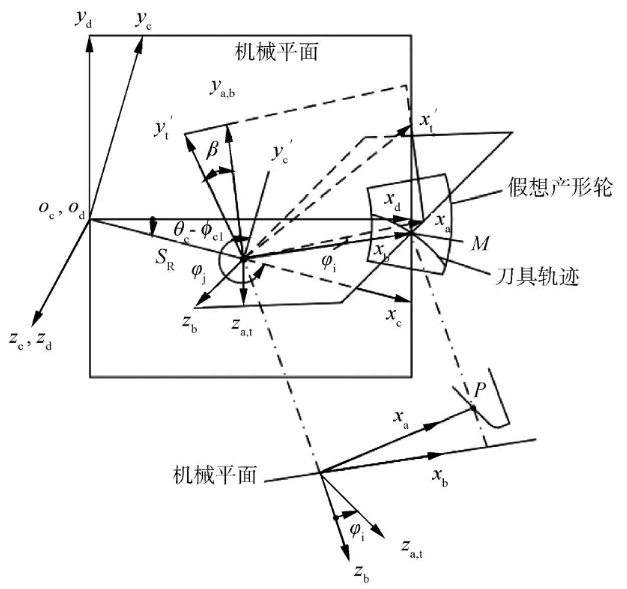
The imaginary generating wheel is often used to explain the formation of bevel gears. It is regarded as a virtual tool and the workpiece rolling quasi hyperboloid gear for generating processing. Its tooth shape is determined by the tool path, and the rotation axis of the imaginary generating wheel is coaxial with the rotation axis of the center of the machine table. In Figure 1, β Is the turning angle of the blade, φ I is the inclination angle of the knife, φ J is the angle set for the tool tilt direction, θ C is the initial setting angle of the shaking table, ϕ C1 is the rotational angle of the cycloidal motion. The tooth surface equation of the hypothetical production wheel is to transfer the blade line equation from the cutter head coordinate system St to the production wheel coordinate system Sd.