
The end face spiral gear coupling is composed of concave tooth part and convex tooth part. The concave tooth part is processed by the external cutting edge of cup-shaped grinding wheel to form concave tooth; the convex tooth part is processed by the inner cutting edge of cup-shaped wheel to form convex tooth. The calculation methods of the design parameters and grinding parameters of the end face spiral gear coupling are given respectively. The cup wheel with straight cutting edge is usually used to process the end face spiral gear coupling. However, in order to prevent the edge contact and improve the load-carrying capacity of the tooth, the tooth profile of the end face spiral gear coupling is modified in this paper, and the cup wheel with arc cutting edge is used for machining. As shown in Fig. 1, Fig. 1 (a) and Fig. 1 (b) are the axial sections of concave and convex gear parts machined by grinding wheel cutting edge with pressure angle of α. The profile modification of tooth height direction can be realized by changing the cutting edge of grinding wheel from straight line to arc with radius RHB (RHB is determined by the height of contact area in tooth height direction).
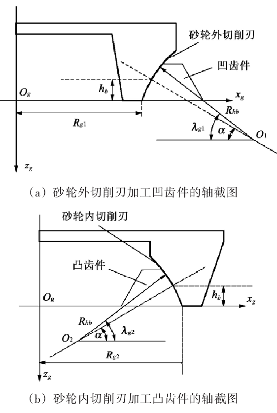
In Figure 1, Rg1 and Rg2 are the tool tip radii for machining concave tooth parts and convex tooth parts, respectively
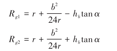
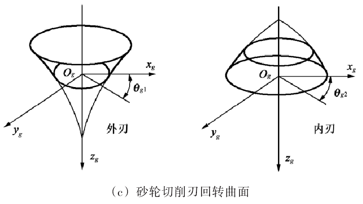
Figure 1 (c) shows the grinding wheel surface generated by the arc cutting edge rotating around the ZG axis of the grinding wheel. The rotation angles of the grinding wheel are θ G1 and θ G2 respectively. Therefore, the rotary surface of grinding wheel is composed of a torus generated by an arc cutting edge. The torus of the machined tooth surface can be determined by the parameters λ G1, λ G2, θ G1 and θ G2 (subscript 1 represents external cutting edge, subscript 2 represents internal cutting edge). In the coordinate system of grinding wheel cutting edge shown in Fig. 1, the grinding wheel surface ∑ G can be expressed by vector function as follows:
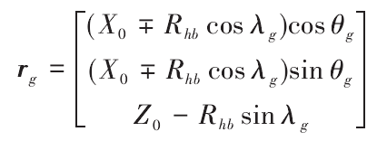
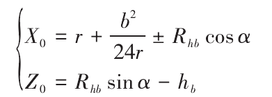
Where, point og is the origin of the grinding wheel coordinate system; x0 and Z0 are the distances from the center of the arc cutting edge to the coordinate axes ZG and XG respectively,
When the end face spiral gear coupling is machined by forming method, the grinding wheel rotates around the axis ZG to finish the grinding of the tooth surface. Therefore, the shape of the tooth surface of the tooth is consistent with that of the cutting surface of the grinding wheel.
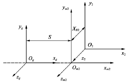
The coordinate system of gear grinding is shown in Fig. 2, SM2 = {om2; XM2, YM2, Zm2} is the coordinate system fixed with the machine tool, S2 = {O2; X2, Y2, Z2} is the coordinate system fixed with the workpiece, and SG = {og, XG, YG, ZG} is the coordinate system fixed with the cutter head. XB2 is the adjustment value of the sliding base of the machine tool, also known as the bed position. When processing the concave and convex teeth of the end face spiral gear coupling, the bed position is equal to the tooth root height of the end face spiral gear coupling, that is XB2 = – Hb.
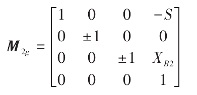
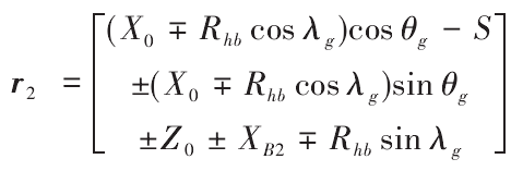
According to the equation RG of the grinding wheel cutting edge surface obtained in the coordinate system SG, the surface equation R2 = m2grg can be obtained, where m2g is the coordinate transformation matrix of the coordinate system SG translated into the coordinate system S2.
It can be obtained by substituting the surface equation of gear tooth surface
The normal vector of tooth surface can be expressed as
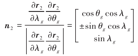
The symbols of “±” and “∓” in each formula correspond to concave tooth parts (machining of external cutting edge of grinding wheel), and the symbols below correspond to convex parts (machining of internal cutting edge of grinding wheel).
In order to measure the tooth profile error between the actual tooth surface and the theoretical tooth surface on the gear measuring center and realize the correction of the tooth profile error, it is necessary to discretize the tooth surface, and calculate the spatial coordinates and normal vectors of the discrete points on the tooth surface. In order to obtain uniform measurement grid of the whole tooth surface, based on the machining principle of the end face spiral gear coupling and the established tooth surface equation, the grid planning is carried out on the theoretical tooth surface of the end face spiral gear coupling, and the position of each point is determined by the parameters θ G and λ g in the tooth surface equation. As shown in Fig. 3, generally, the discrete points of tooth surface are 9 columns in the direction of tooth length and 5 rows in the direction of tooth height, with a total of 9 × 5 discrete points. The discrete points are represented by P (L, m), and L = 1 ~ 9, M = 1 ~ 5.
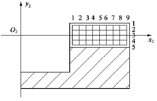
The tooth profile of the end face spiral gear coupling is curved in the direction of tooth length and tooth height. Therefore, as long as the angle parameters θ g and λ G are equally divided, the uniform discrete points can be obtained. Among them, the parameter θ G is determined by radial cutter position s, nose radius RG, outer cone distance re and inner cone distance RI. The maximum value of the parameter θ G is obtained when the outer cone distance is taken, and the minimum value of the parameter θ G is obtained when the inner cone distance is taken; it can be seen from Fig. 1 (a) and Fig. 1 (b), that the maximum value of parameter λ G is obtained at the tooth top, and the minimum value is obtained at the tooth root. By substituting the angle parameters θ g and λ G corresponding to each discrete point into the tooth surface equation and normal vector equation, the spatial coordinates and normal vector of each discrete point can be obtained.