(1) Stress analysis method of spiral bevel gear die
DEFORM-3D software has two methods for stress analysis of spiral bevel gear die: uncoupled method and coupled method. The uncoupled method can only analyze the stress distribution of spiral bevel gear die at a certain time. If the whole forming process is analyzed, that is, the stress analysis of the spiral bevel gear die at a certain time of the forming process, it is necessary to import the deformed spiral bevel gear die into the pre processor again in the pre-processing, and then solve the spiral bevel gear die stress at another time by interpolating the load on the forming blank to the spiral bevel gear die, so as to repeat this step until the last step. For complex parts, the coupling method has a large amount of calculation and is difficult to converge. Due to the high calculation efficiency and easy convergence of the decoupling method, the idea of deform to solve the stress of spiral bevel gear die in the die forging process is generally to carry out the die forging molding process in the conventional sense first. When this process is completed, the spiral bevel gear die is regarded as an elastic deformation body, and the forming load of the blank is mapped to the forming die through interpolation calculation, so as to calculate the die stress.
(2) Maximum equivalent stress of spiral bevel gear die
Fig. 1 shows the variation curve of the maximum equivalent stress of spiral bevel gear die with forging stroke under the above conditions. It can be seen that the equivalent stress of spiral bevel gear die increases with the increase of stroke, and the equivalent stress increases slowly in the first half of stroke, and increases sharply in the final forming stroke.
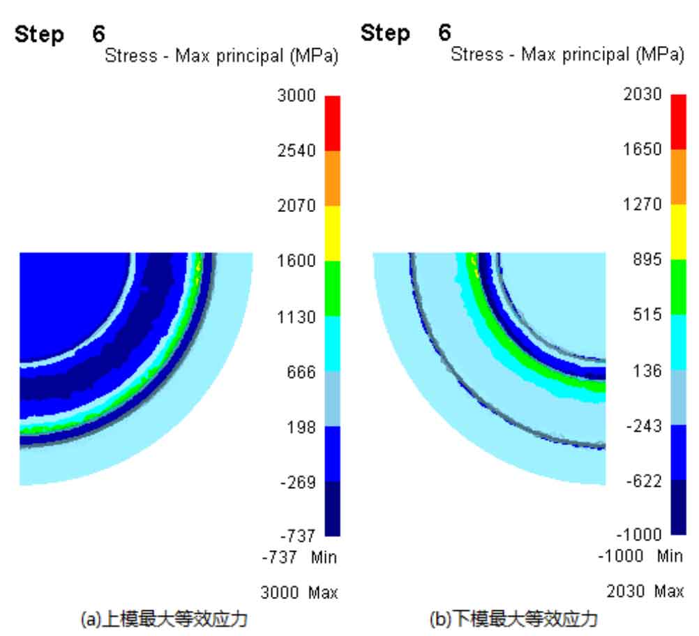
The maximum equivalent stress of upper and lower dies of hot die forging is shown in Fig. 2 (a) and Fig. 2 (b) respectively. It can be seen from the figure that the upper and lower die parameters are in serious stress concentration, and the high stress area is mainly concentrated in the upper and lower die, there is serious stress concentration, and the high stress area is mainly concentrated in the fillet of the upper and lower die, and there are tensile stress and compressive stress near the fillet. This can easily lead to the cracking of the fillet. The maximum equivalent stress of the upper die is 3000mpa and the maximum equivalent stress of the lower die is 2030mpa.
Figure 3 shows the physical drawing of the gear forging die with cracking failure in the gear factory. It can be seen from the figure that the forging cracking parts are all the fillet parts, which also shows that the stress simulation of the spiral bevel gear die can accurately reflect the cracking parts of the spiral bevel gear die.


