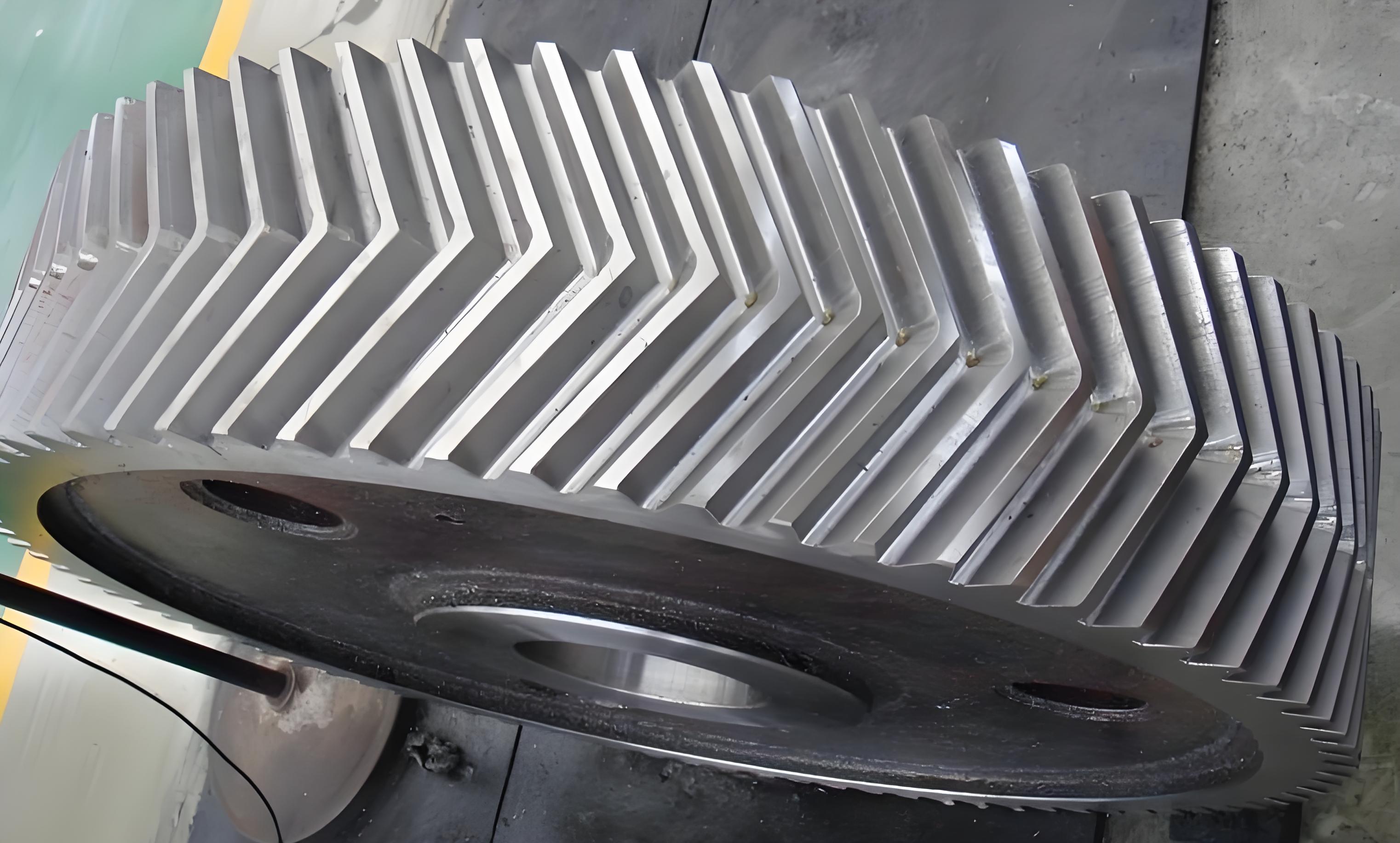
Herringbone gears, characterized by their high load capacity and minimized axial forces, are widely used in heavy-duty applications such as marine propulsion and aerospace systems. The symmetry of tooth contact lines relative to the central plane critically influences load distribution uniformity, vibration, and noise generation during operation. This paper proposes a novel symmetry evaluation method based on contact line analysis to address manufacturing-induced asymmetries in herringbone gears.

1. Contact Line Definition and Symmetry Metrics
The instantaneous contact line of herringbone gears is defined as the intersection between the base cylinder tangent plane and the tooth flank. For a perfect herringbone gear with helix angle $\beta$, the contact line equation in the coordinate system $T’RZ’$ is expressed as:
Left-hand flank:
$$ Z’ = \tan(90^\circ – \beta_b)T’ + b_L $$
Right-hand flank:
$$ Z’ = -\tan(90^\circ – \beta_b)T’ + b_R $$
where $\beta_b$ represents the base circle helix angle calculated by:
$$ \beta_b = \tan^{-1}\left(\tan\beta \cdot \cos\left[\tan^{-1}\left(\frac{\tan\alpha_n}{\cos\beta}\right)\right]\right) $$
2. Symmetry Error Metrics
Four key symmetry indicators are established:
| Metric | Definition | Formula |
|---|---|---|
| Tooth Symmetry Error ($f_{Ai}$) | Axial deviation of contact line intersection | $f_{Ai} = |Z_i – Z_0|$ |
| Adjacent Tooth Error ($f_{Au}$) | Maximum difference between adjacent teeth | $f_{Au} = \max|f_{Ai} – f_{A(i+1)}|$ |
| Total Symmetry Error ($F_A$) | Range of symmetry deviations | $F_A = \max(f_{Ai}) – \min(f_{Ai})$ |
| Mean Symmetry Error ($f_{As}$) | Average deviation across all teeth | $f_{As} = \frac{1}{N}\sum_{i=1}^N f_{Ai}$ |
3. Measurement Methodology
The measurement system employs coordinate transformation and least-squares fitting:
Data acquisition:
$$ P_{\theta_j} = \begin{bmatrix}
T_j \\
R_j \\
Z_j
\end{bmatrix}, \quad j=1,2,…,n $$
Contact line fitting:
$$ \min \sum_{j=1}^n [Z_j – (kT_j + b)]^2 $$
For a sample herringbone gear with parameters:
| Parameter | Small Module | Large Module |
|---|---|---|
| Module (mm) | 2.2 | 3.9 |
| Teeth Count | 27 | 27 |
| Helix Angle (°) | 30 | 30 |
| Tooth Width (mm) | 30 | 47 |
4. Experimental Validation
Comparative results between contact line method and section method:
| Metric | Contact Line Method | Section Method | Improvement |
|---|---|---|---|
| Measurement Time (min) | 105 | 10 | -90.5% |
| $F_A$ Accuracy (μm) | ±2.4 | ±3.2 | +33.3% |
| $f_{Au}$ Consistency | 0.007mm | 0.015mm | +53.3% |
The contact line method demonstrates superior accuracy despite longer measurement duration, with uncertainty analysis showing:
$$ u(f_{As}) = \sqrt{\frac{\sum_{i=1}^n (f_{Ai} – \bar{f_A})^2}{n(n-1)}} $$
For the large module gear:
$$ u(f_{As}) = 0.0003\text{mm}, \quad U_{95\%} = 0.0006\text{mm} $$
5. Software Implementation
The measurement system architecture integrates:
| Component | Function |
|---|---|
| Motor Control | Precision positioning with 0.1μm resolution |
| Data Acquisition | Simultaneous 4-axis sampling at 1kHz |
| Error Compensation | Thermal drift correction <1μm/m |
The software workflow implements:
$$ \text{Alignment} \rightarrow \text{Scanning} \rightarrow \text{Fitting} \rightarrow \text{Evaluation} $$
6. Conclusion
This contact line-based methodology effectively addresses herringbone gear symmetry evaluation challenges, providing:
- Comprehensive error metrics reflecting operational performance
- Superior accuracy compared to conventional section methods
- Quantifiable uncertainty below 0.6μm for critical parameters
Future work will focus on real-time compensation algorithms and standardized evaluation protocols for industrial applications of herringbone gears.
