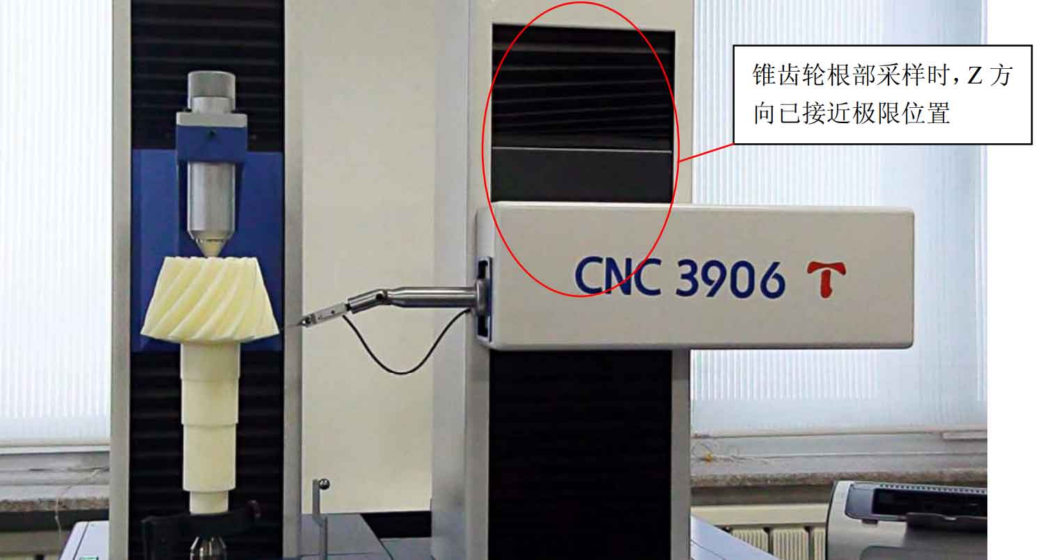
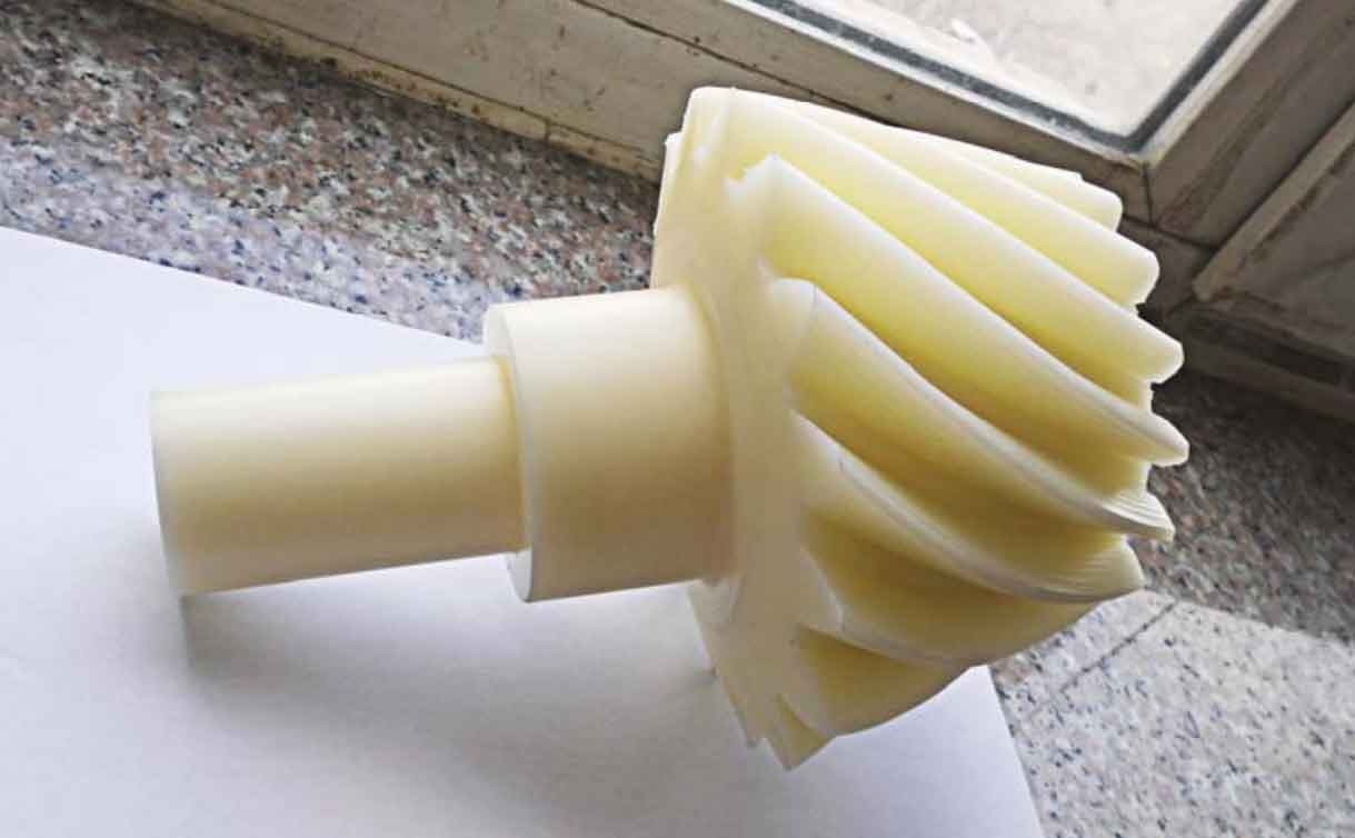
First press the green start button in Figure 1 to start the gear measuring center, and then start the supporting computer. Start the GIS software system on the interface of microcomputer, create a new bevel gear database to be tested, and input the key parameters of spiral bevel gear. Before collecting the tooth profile parameters of bevel gear, the system calibration and zero correction must be carried out first. As shown in Figure 1, calibrate the distance between the standard ball and the rotation center of the workbench. Then remove the standard mandrel with a diameter of 20mm, install the spiral bevel gear to be tested, correct the zero point of the system, and calibrate the distance between the installation base surface of the bevel gear to be tested and the center of the standard ball. However, because the bevel gear shaft to be tested is too long, it exceeds the measuring range of 3906t gear measuring center in Z direction, as shown in Figure 2. Therefore, the shaft part of spiral bevel gear is shortened, as shown in Figure 3.
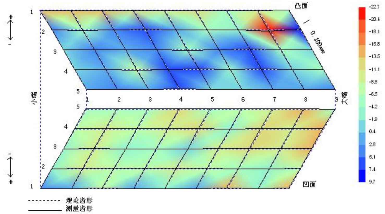
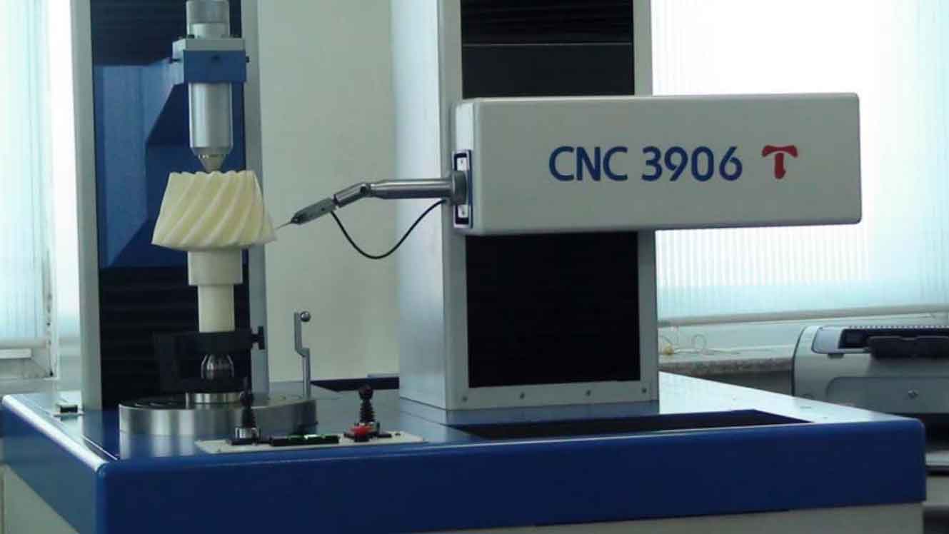
After the shaft part of the spiral bevel gear to be measured is shortened, the system calibration and zero point correction shall be carried out again, and then the lower end face of the back cone of the spiral bevel gear shall be used as the installation base surface to calibrate the distance between the base surface and the center of the standard ball. On the basis of the above work, the sampling of the bevel gear tooth surface to be measured and the measurement of the normal deviation of the tooth surface can be carried out. Fig. 4 is a picture of a certain moment in the process of sampling and deviation measurement of spiral bevel gear. The measured normal deviation of tooth surface is shown in Fig. 5. The specific values of the normal deviation of the spiral bevel gear tooth surface measured by the 3906t gear measuring center are listed in the table.
According to the measured tooth surface normal deviation diagram and the corresponding numerical table, the normal deviation of spiral bevel gear machined by the proposed new two-axis linkage milling method is between -0.0227mm ~ 0.0097mm. The tooth cutting experiment and the measurement results of tooth surface deviation further confirm the feasibility of the principle prototype of the developed two-axis linkage tooth cutting machine tool and the new two-axis linkage tooth cutting method of spiral bevel gear. The next step will further improve the transmission accuracy of the gear cutting machine tool and the stability during gear cutting, further refine the generation line of the tooth surface and use the ball head grinding wheel for grinding and finishing. The spiral bevel gear generated by this cutting will further reduce the tooth surface deviation and improve the tooth surface precision.