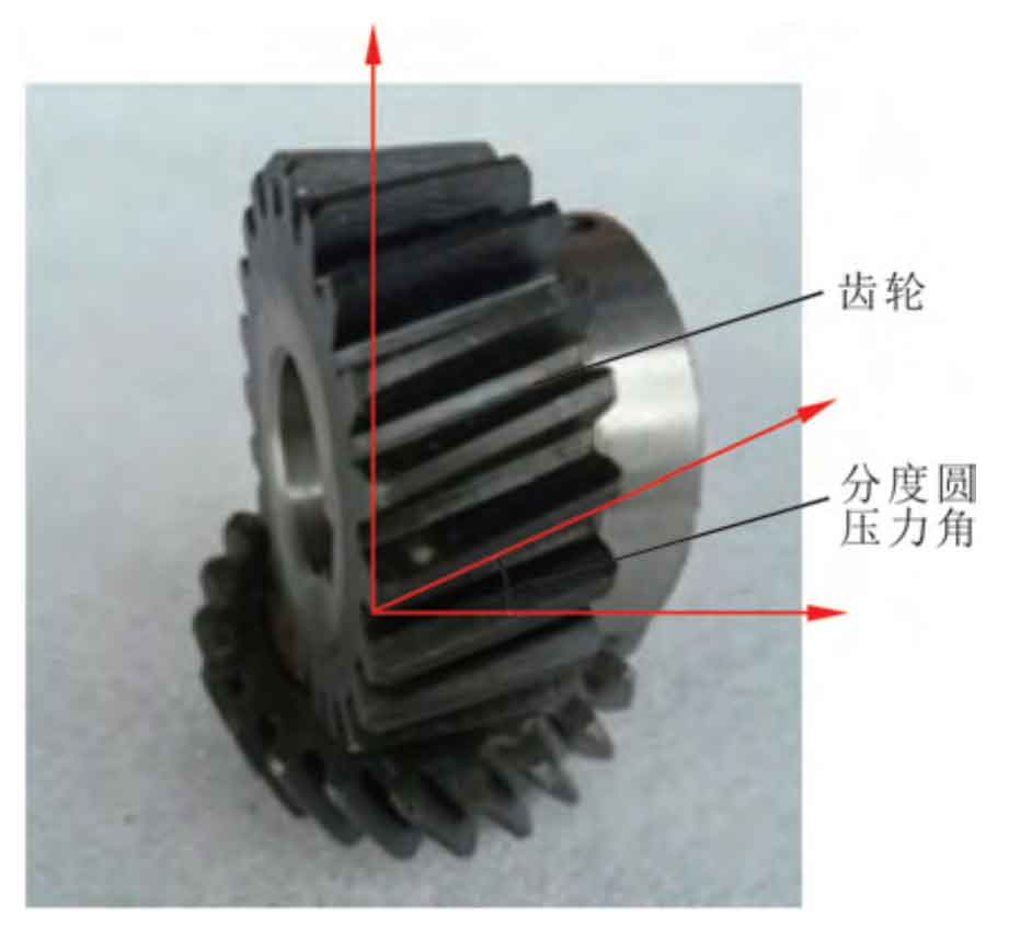
In order to verify the effectiveness of the measuring system for the machining parameters of cylindrical helical gears with manufacturing errors, the standard involute helical gears are selected as the experimental objects. The structural shape is shown in the figure, and the relevant parameters of the cylindrical helical gear are shown in the table.
| Parameter classification | Parameter name | Standard parameter description |
| Measured gear parameters | Number of gears | 95 |
| Measured gear parameters | Modulus | 2 |
| Measured gear parameters | Pressure angle of graduation circle | 25° |
| Measurement parameters | Gray threshold | 113 |
| Measurement parameters | Width coefficient of tooth profile measurement area | 0.39 |
| Measurement parameters | Image pixel equivalent | 18.021 |
| Measurement parameters | Gear center calibration image coordinates | (1324. 12,1324. 12) |
| Measurement parameters | Single tooth photography beat | 0.7s |
The processing parameter measurement system of cylindrical helical gear considering manufacturing error and the traditional numerical control cylindrical helical gear measurement system are used to measure. When applying the newly designed measuring system, the standard parameters of the cylindrical helical gear to be measured shall be input in turn, and the measuring parameters under the same experimental environment shall be set in the system. Then, the cylindrical helical gear to be measured shall be cleaned and installed on the system, the image position and object distance shall be adjusted, and the system shall be started for measurement.