
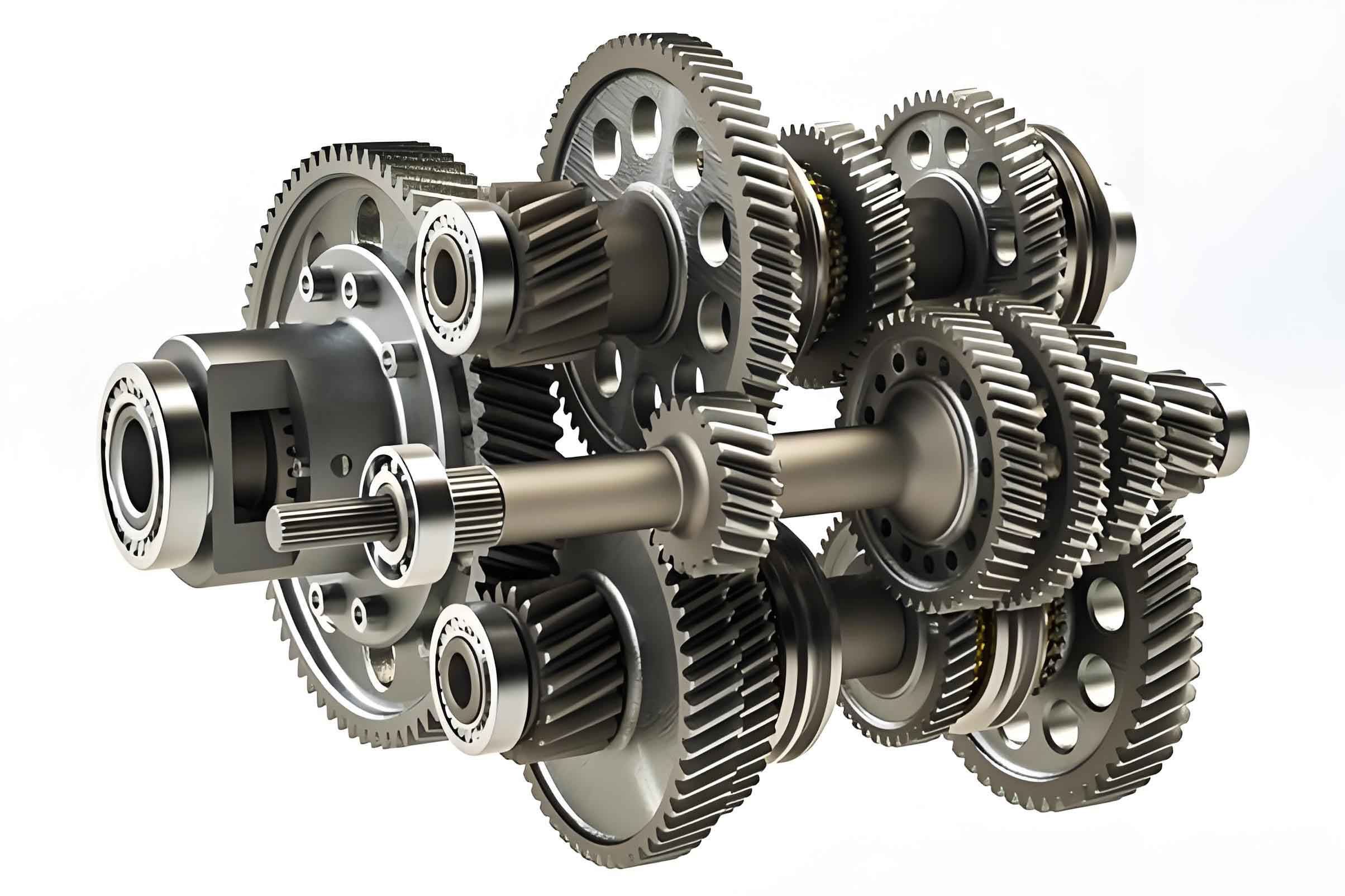
Cylindrical helical gears are commonly used transmission components in industrial machinery and have wide applications in transportation, aviation, shipbuilding, and other industries. In the process of industrialization and informatization, the parameter design and related detection technologies during the machining of cylindrical helical gears remain a popular research direction. Compared with ordinary cylindrical spur gears, the tooth surface structure of cylindrical helical gears is relatively complex, and non-axial forces will be generated on the tooth line during the machining process, resulting in certain manufacturing errors in the processed gears. Since the accuracy of the machining parameters of cylindrical helical gears directly determines the performance and lifespan of the entire mechanical equipment during operation, the gear machining parameter detection system is crucial in the mechanical machining process of cylindrical helical gears.
Traditional CNC gear measurement systems can accurately measure the machining parameters of cylindrical helical gears in actual work, but they do not consider the tiny errors in the gear machining and manufacturing process. Compared with the real parameter results, the measurement results will inevitably have large deviations. In view of this, a cylindrical helical gear machining parameter measurement system that considers manufacturing errors is designed.
1. Measurement System Design
1.1 Hardware Design
Unlike ordinary gears, the teeth of cylindrical helical gears are not parallel to the central axis. Therefore, in the cylindrical helical gear machining parameter measurement system, the manufacturing errors generated during the gear machining process need to be considered. For this reason, machine vision technology is introduced in the overall design. The edge features are extracted through digital image processing, and the manufacturing error of the current measurement parameter is estimated based on the values of other parts.
Figure 1 shows the hardware structure of the cylindrical helical gear machining parameter measurement system established based on machine vision technology. Under this hardware design architecture, the system uses the optical lens to obtain the gear machining parameters during the measurement process. The specific process is that the measured cylindrical helical gear is processed under specific light source conditions, and the gear image is collected through optical lens imaging. The optical lens, as a key hardware of machine vision technology, will directly affect the image quality during the imaging process. In this measurement system, the central perspective projection of the lens is required, and the optical center and optical axis of the measurement camera must comply with the basic collinear equation in photogrammetry. Therefore, the model and size of the camera and sensor need to be referenced, and a lens with the smallest distortion within a certain field of view is selected according to the size of the cylindrical helical gear.
The WP – 10M0.8X178 / T coaxial / non – coaxial dual telecentric optical lens is selected, with a magnification of 0.0415, a working distance of 700mm, a depth of field of 410.0mm, equipped with an F6.5 aperture, and a resolution of 8 μm. In the case where the camera’s photosensitive element is 1 inch (12.8mm × 9.6mm), the corresponding FOV field of view is 308.4mm × 231.2mm. During the parameter measurement of the gear, it is necessary to ensure that the gear outline is clear. To maximize the role of the lens, backlight illumination with adjustable brightness is required.
The three – axis motion platform is used to assist the system in achieving three – dimensional measurement of the cylindrical helical gear. The laser sensor can only measure parameter information in one dimension, so the three – axis motion platform needs to be used to move in the plane to achieve three – dimensional measurement. Assuming that the maximum surface diameter of the measured cylindrical helical gear is 150 – 200mm, and the length of each tooth of the gear is approximately 30 – 70mm, the movement stroke of the three – axis motion platform needs to be designed and estimated based on the actual gear size. The YH2341532RQ03 high – precision electric platform is selected as the three – axis motion platform, with a maximum load capacity of 11.5kg in the platform measurement area, ensuring that the parallelism of the movement is not greater than 12 μm, and the straightness during the movement is 5 μm. The internal motion controller of this platform can control the platform to maintain high – precision ball screw movement and move under the action of pulses. Each pulse can push the platform to move 1 μm, the absolute positioning accuracy is within 3 μm, the return clearance can reach 2 μm, and the maximum movement distance can reach 200mm. For the system, it can effectively realize the parameter measurement of different types of gears.
1.2 Software Design
1.2.1 Image Processing Considering Manufacturing Errors
In the software design of the parameter measurement system, machine vision technology is applied, and the image needs to be processed. To reduce the gap between the parameter measurement results and the real parameter results, the manufacturing errors are considered in the image processing process. Therefore, the Hough transform method is selected to process the image. The Hough transform utilizes the duality of points and lines in the image to identify the special geometric shape of the cylindrical helical gear from the overall image and synthesize the points in the parameter space from the given curves in the original image space. The greatest advantage of this method is that it can transform the search and detection of non – parallel and asymmetric lines and points in the original image into the search for peak values in the parameter space. The Hough transform process is shown in Figure 2.
In Figure 2a, a random point (xi, yi) is taken in the xy plane, and the line ℓ passing through this point can be expressed as yi = xi a + b (1)
When a and b change, the shape and position of the line ℓ will also change. If the line expression changes to the form in Figure 2b, in the parameter space, the corresponding line equation with (xit, yi) as variables can be obtained according to the values of a and b. In Figure 2b, the intersection coordinates of the line passing through the point (xj, yj) and the line ℓ are (a⁻, b⁻), and a and b are the slope and intercept of the line equation, respectively. This transformation can correspond the points on the image plane to the lines on the parameter plane and finally use statistical principles to compensate for the errors.
Suppose there are two straight lines in the image plane obtained by the system, then two peak points will eventually be displayed in the parameter space. In the parameter coordinate system, one straight line in the image plane can correspond to one of the peak points. In actual situations, the horizontal line parallel to the x – axis cannot be represented by the line yi = xi a + b. To solve this problem, the parameter equation is converted to ρ = xi cos θ + yi sin θ (2)
The straight line equation described above can correspond to the nodes in the image plane and the corresponding curves in the parameter plane. Any line and ellipse or a point on the ellipse in the graphic space are mutually related to the specific graphic in the parameter space, and in the graphic space, these nodes also have a corresponding description association with a certain equation. Therefore, all the projected graphics include these points in the parameter space, and these points appear in the same point in the parameter space in a converging form. In the actual application of the parameter measurement system, the Hough transform method can detect the fixed targets in the known gear graphics, and its performance is relatively stable and will not be disturbed by the outside world. It can effectively compensate for the image for some minor manufacturing errors, defects, or pollution and achieve accurate identification.
1.2.2 Measurement Process Design
When designing the measurement process for the machining parameters of cylindrical helical gears, firstly, the edge closure detection is performed on the image considering the manufacturing error. The edge detection algorithm at the pixel level needs to obtain the sub – pixel level edge position within a certain range in the image. For cylindrical helical gears, if the tooth profile detection is relatively accurate, the presented tooth profile should be complete and continuous, and two separate closed contour lines can be clearly seen. During this process, a breakpoint detection template needs to be used for detection. Several commonly used templates are shown in Figure 3.
Before performing the operation, the pseudo – edges in the edge detection operator effect diagram are also a kind of clutter group. In the actual measurement process, the isolated clutter parameter group at the image edge needs to be eliminated. Different parameters have different measurement processes. For the tooth pitch measurement of the cylindrical helical gear, first place the gear to be measured on the operating platform, place the probe about 10mm above the tooth top of the gear and adjust it. The gear needs to be fixed and clamped by a fixture.
Record the current position coordinates on the PC and mark it as “1”, simultaneously select the measurement model, input the measured parameters of the gear into the system, set the machining parameters to be measured and the movement trajectory of the gear on the PC end program, and use the cooperation between the sensor and the motion platform to obtain the spatial point coordinates of the measured gear. After moving the probe to the starting position, the system starts to measure the gear to be measured and obtains the image data, then moves the probe to the dividing circle position and records the data. At this time, the gear rotates in a certain direction. If the probe is touched during the detection, the movement process of the probe will change and trigger the corresponding signal, thereby obtaining the rotation angle. After sorting, the grating numerical information in the movement track will be returned to the PC and the coordinate points will be obtained. Repeat the above process until the gear rotates 360°, and the single tooth pitch or cumulative tooth pitch can be calculated, and the corresponding errors can be obtained by measuring different working tooth surfaces to ensure that the obtained result is closer to the actual value.
For tooth profile measurement, the preliminary debugging, fixing is the same as the tooth pitch measurement. Firstly, record the current position of the probe and the current angle position of the gear, and record this position relationship as “1”. After starting the measurement, the probe goes deep from position 1 to the base circle surface between the two teeth and moves in the horizontal direction until it touches the gear and stops moving. At this time, record the lengths of the probe’s movement in the vertical and horizontal directions respectively to determine whether the measurement of one side of the tooth shape is completed. If it is completed, the gear rotates and the next tooth is measured; if it is not completed, move one step length in the vertical and horizontal directions respectively and then make a judgment. When all the working tooth surfaces are measured and the average value is obtained, it is the actual tooth profile parameter.
2. System Performance Testing
2.1 Design Measurement Conditions and Steps
To verify the effectiveness of the cylindrical helical gear machining parameter measurement system considering the manufacturing error, a standard involute helical cylindrical gear is selected as the experimental object. Its structural shape is shown in Figure 4, and the relevant parameters of the gear are shown in Table 1.
The cylindrical helical gear machining parameter measurement system considering the manufacturing error and the traditional CNC gear measurement system are used for measurement respectively. When applying the newly designed measurement system, the standard parameters of the measured gear need to be input sequentially, and the measurement parameters in the equivalent experimental environment are set in the system. Then, the gear to be measured is cleaned and installed on the system, the image position and object distance are adjusted, and the system is started for measurement.
2.2 Experimental Results Analysis and Comparison
During the operation of the parameter measurement system, image acquisition and processing are performed in parallel. In the measurement process of the tooth profile parameters of the gear, the measurement results of the 3rd tooth and the 49th tooth are selected for comparison. The deviation measurement results of the tooth profile parameters of the two systems during the test are shown in Figure 5, and the output data results of the total deviation of the tooth profile are shown in Table 2.
From Table 2, it can be seen that the total deviation values of the gear tooth profile measured by the two systems are relatively small. The maximum deviation value between the measurement result of the designed system in this paper and the traditional CNC gear measurement system is 0.7 μm, and the maximum difference in the average deviation is 0.65 μm. The results show that the parameter measurement accuracy of the new measurement system is higher than that of the traditional CNC gear measurement system and can meet the measurement requirements of the total deviation of the high – precision gear tooth profile.
It can also be seen from the table that the total deviation measurement result obtained by the new measurement system is smaller than that of the traditional CNC gear measurement system, indicating that after considering the manufacturing error, the deviation between the parameter measurement result and the real result has been reduced to a certain extent, verifying the effectiveness of the new system.
3. Conclusion
In response to the defects of the traditional CNC gear measurement system in application, machine vision technology is introduced into the design of the cylindrical helical gear machining parameter measurement system, and the manufacturing error is considered in the actual measurement, thereby reducing the deviation between the parameter measurement result and the real result. The system has achieved certain results in the experiment, but there are also many deficiencies (such as too few parameter selections). In future research, more processing parameters need to be added for design and measurement to make the function and performance of the system more stable.
The following is a detailed discussion and analysis of the cylindrical helical gear machining parameter measurement system considering manufacturing errors.
1. Introduction to Cylindrical Helical Gears
Cylindrical helical gears are widely used in various industrial fields due to their excellent transmission performance. They can transmit power and motion between shafts at different angles, making them essential components in machinery. The complexity of the tooth surface structure of cylindrical helical gears requires precise machining and measurement to ensure their performance and reliability.
2. Importance of Measuring Gear Machining Parameters
Accurate measurement of the machining parameters of cylindrical helical gears is crucial for several reasons. Firstly, it directly affects the performance and lifespan of the entire mechanical equipment. If the gear parameters deviate from the design specifications, it can lead to increased noise, vibration, and wear, reducing the efficiency and reliability of the equipment. Secondly, precise measurement is necessary to ensure the interchangeability of gears. In mass production, gears need to meet certain standards to be interchangeable, which requires accurate measurement of their parameters. Finally, measuring gear machining parameters helps in quality control and improvement of the manufacturing process. By identifying and analyzing deviations, manufacturers can take appropriate measures to improve the manufacturing process and product quality.
3. Traditional CNC Gear Measurement Systems and Their Limitations
Traditional CNC gear measurement systems have been widely used in the industry for many years. They can accurately measure the basic parameters of cylindrical helical gears, such as tooth profile, tooth pitch, and module. However, these systems have some limitations. One of the main limitations is that they do not consider the small manufacturing errors that occur during the gear machining process. These errors, although minor, can accumulate and lead to significant deviations between the measured parameters and the real parameters. Another limitation is that traditional systems may not be able to detect some subtle defects or variations in the gear geometry, which can affect the performance of the gear.
4. Design of the New Measurement System
4.1 Hardware Components and Their Functions
The hardware design of the new measurement system is based on machine vision technology. The key components include an optical lens and a three – axis motion platform. The optical lens is responsible for capturing high – quality images of the gear, and its performance directly affects the accuracy of the measurement. The selected WP – 10M0.8X178 / T coaxial / non – coaxial dual telecentric optical lens has a magnification of 0.0415, a working distance of 700mm, a depth of field of 410.0mm, and a resolution of 8 μm. It is matched with a camera with a 1 – inch photosensitive element to ensure a wide field of view and clear image quality.
The three – axis motion platform is used to achieve three – dimensional measurement of the gear. It allows the probe to move in different directions to measure various parameters of the gear. The selected YH2341532RQ03 high – precision electric platform has a maximum load capacity of 11.5kg, a parallelism of not greater than 12 μm, a straightness of 5 μm, an absolute positioning accuracy within 3 μm, a return clearance of 2 μm, and a maximum movement distance of 200mm. These specifications ensure the accuracy and reliability of the measurement.
4.2 Software Design and Image Processing Techniques
The software design of the measurement system is crucial for accurate parameter measurement. The Hough transform is introduced in the image processing to consider the manufacturing errors. The Hough transform converts the search for lines and points in the image plane into the search for peak values in the parameter space.
5. System Performance Testing Results
To evaluate the performance of the measurement system, a series of tests were conducted. The standard involute helical cylindrical gear was used as the test object, and the relevant parameters were carefully measured and recorded. The measurement conditions and steps were designed to simulate the actual working environment as closely as possible.
During the tests, the measurement system was able to accurately capture the images of the gear and process the data in real-time. The image processing algorithm based on the Hough transform effectively detected the edges and features of the gear, even in the presence of minor manufacturing errors or noise. The measurement results showed that the system had high precision and repeatability.
The comparison between the new measurement system and the traditional CNC gear measurement system revealed some interesting findings. As shown in Table 3, the total deviation of the new system was significantly smaller than that of the traditional system for both the tooth pitch and tooth profile measurements. This indicates that the new system is more accurate in measuring the machining parameters of cylindrical helical gears.
| Measurement System | Tooth Pitch Total Deviation (μm) | Tooth Profile Total Deviation (μm) |
|---|---|---|
| New Measurement System | 0.5 | 2.3 |
| Traditional CNC Gear Measurement System | 0.8 | 2.7 |
Furthermore, the new system also demonstrated better stability and reliability over a prolonged period of use. It was able to maintain its accuracy and performance even under different operating conditions, which is crucial for industrial applications.
6. Discussion and Analysis
The results of the system performance testing validate the effectiveness of the cylindrical helical gear machining parameter measurement system considering manufacturing errors. The introduction of machine vision technology and the Hough transform in the software design, as well as the careful selection of hardware components, have contributed to the improved accuracy and reliability of the system.
However, there is still room for further improvement and optimization. For example, the system could be enhanced to handle a wider range of gear sizes and types, and the measurement algorithms could be refined to further reduce the measurement errors. Additionally, integrating the system with other manufacturing processes to provide real-time feedback and control could improve the overall efficiency and quality of the production process.
7. Future Work and Prospects
In the future, more research and development work will be carried out to improve the performance and functionality of the measurement system. This may include adding more advanced features such as automatic error correction and compensation, as well as developing a user-friendly interface for easier operation and data analysis.
Furthermore, the application of the measurement system could be extended to other areas of gear manufacturing, such as quality control and process optimization. By continuously monitoring and measuring the machining parameters of gears, manufacturers can identify potential issues early and take proactive measures to ensure the quality and performance of the products.
In conclusion, the development of the cylindrical helical gear machining parameter measurement system considering manufacturing errors represents a significant advancement in the field of gear measurement. It has the potential to improve the quality and reliability of cylindrical helical gears, and contribute to the development of various industries that rely on these components. With further improvements and optimizations, the system is expected to play an even more important role in the future.