
The shaking table bevel gear cutting machine used in the previous design is a virtual machine and cannot be used for actual machining. It must be converted to a real machine. Therefore, the mechanical settings will be derived based on the new 6-axis CNC bevel gear cutting machine, as shown in the figure.
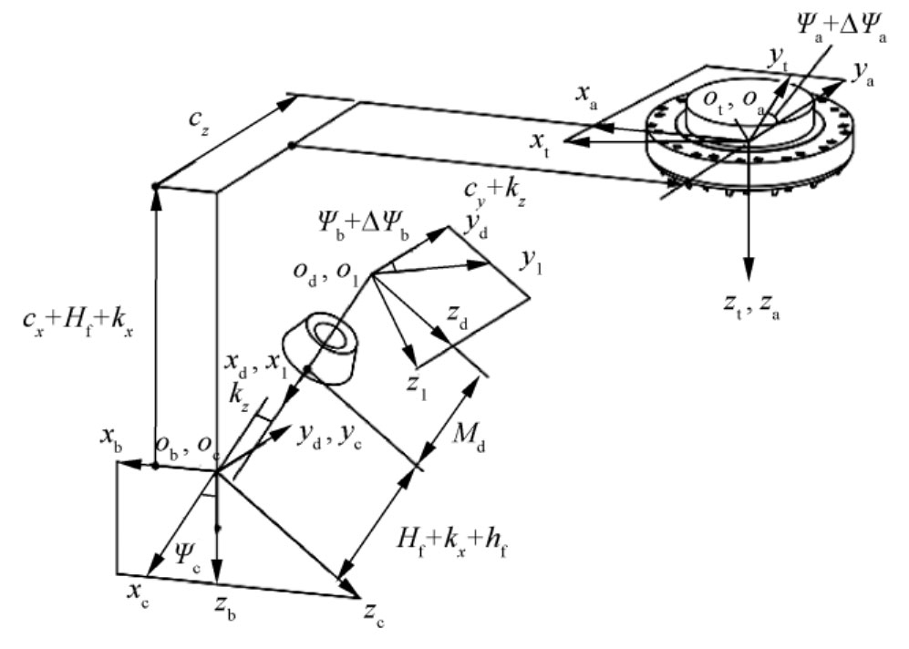
Ψ B – inclination angle of the workpiece rotation axis; Ψ A – Tool rotation angle; Ψ C – inclination angle of the workpiece;
ΔΨ A – Angle increment of tool rotation axis; ΔΨ B – The angle increment of the workpiece rotation axis;
Md – installation distance of gear blank; Kx, kz – mechanical constant
To ensure that the bevel gear tooth surface processed on a 6-axis CNC machine tool is the same as that processed on a traditional shaking table machine tool, the coordinate conversion matrix from the tool coordinate system to the workpiece coordinate system must be consistent in the coordinate systems of both machines. Given the coordinate conversion matrix between the shaking table machine tool and the 6-axis CNC gear cutting machine, the mechanical settings applicable to the 6-axis CNC gear cutting machine are obtained under the condition that the Mga and Ml ′ t ′ matrices are equal. Represent the Mga matrix as element a.
When performing surface rolling machining on a 6-axis CNC gear cutting machine, the tool rotation axis rotates at a fixed speed, increasing the angle increment on the original tool rotation axis ΔΨ Compensate in the negative direction to the workpiece axis.