
In hydraulic power steering systems for commercial vehicles, steering shaft gears play a critical role in torque transmission, demanding high precision and durability. However, during post-carburizing grinding processes, grinding cracks frequently emerge, compromising gear integrity and performance. These grinding cracks manifest as intersecting networks at the tooth root, extending toward the involute surface, and often evolve into parallel patterns over time. To address this, I investigated the root causes using a multi-faceted approach, including chemical composition analysis, microstructural examination, and microhardness testing. The findings revealed that grinding cracks stem from thermal and phase-transformation stresses during grinding, which exceed the material’s tensile strength. By optimizing heat treatment and grinding parameters, and rethinking gear design, I successfully mitigated these defects, enhancing reliability.
Chemical and Microstructural Analysis of Failure
Initial analysis focused on the base material, 20CrMnTi steel, to rule out compositional flaws. Chemical testing confirmed compliance with standards, as shown in Table 1. This eliminated material inconsistency as a cause for grinding cracks.
| Element | C | Si | Mn | P | S | Cr | Cu | Ti |
|---|---|---|---|---|---|---|---|---|
| Standard Range | 0.17–0.23 | 0.17–0.37 | 0.80–1.10 | ≤0.035 | ≤0.035 | 1.00–1.30 | ≤0.20 | 0.04–0.10 |
| Measured Value | 0.21 | 0.25 | 0.92 | 0.01 | 0.01 | 1.03 | 0.007 | 0.06 |
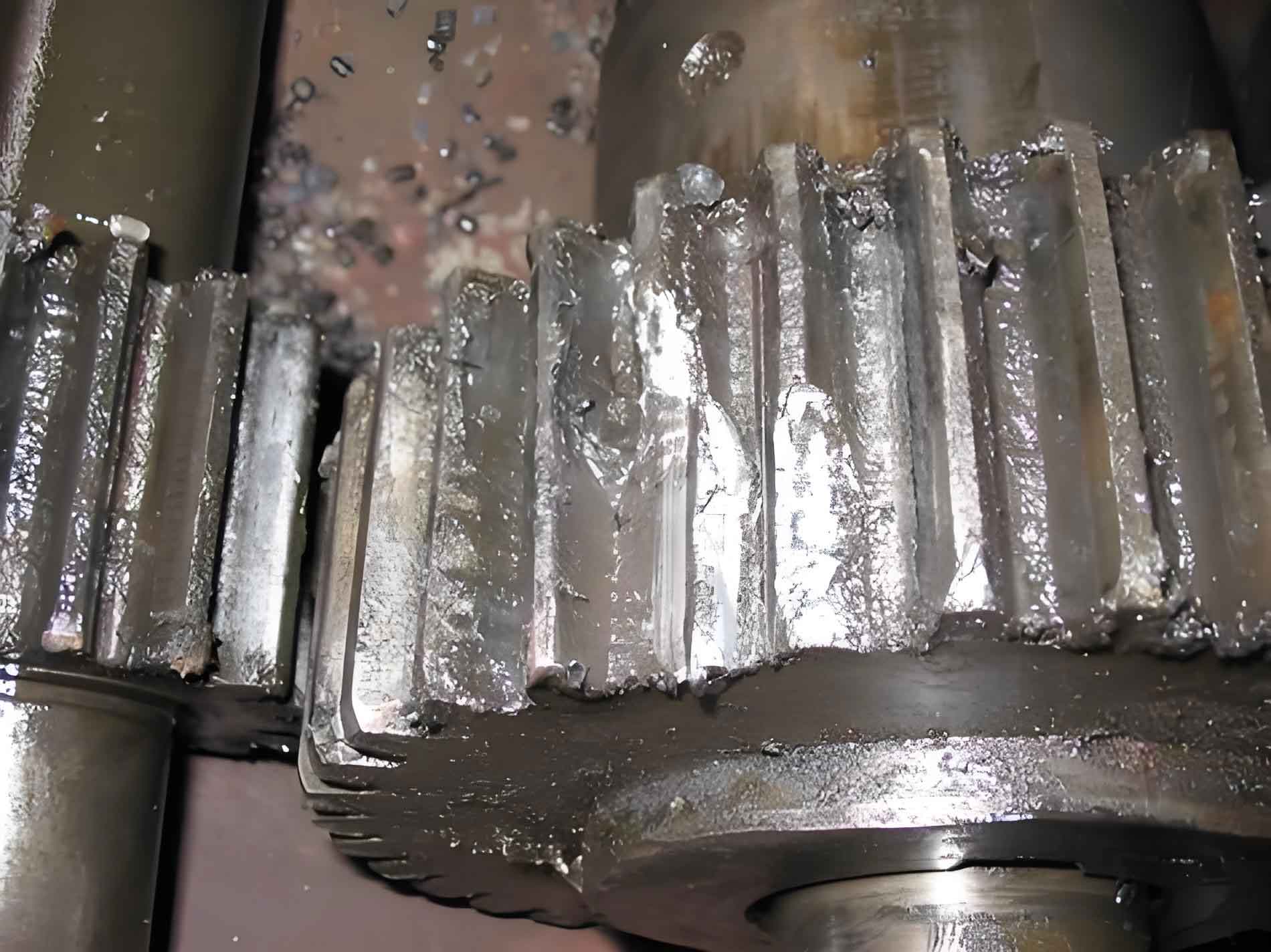
Macroscopic inspection via magnetic particle testing showed no cracks after carburizing and quenching, but post-grinding, distinct grinding cracks appeared. These originated at the tooth root, propagating perpendicular to the grinding direction before aligning parallel on the involute surface. Microstructural analysis further clarified the issue: pre-grinding samples exhibited tempered martensite with dispersed carbides, rated at level 1.5–2. Post-grinding, however, revealed a “white layer” of secondary quenched martensite, underlain by tempered troostite and low-carbon martensite, indicating severe grinding burn. This microstructural alteration was pivotal in crack initiation.
Microhardness profiling provided quantitative evidence of grinding-induced damage. Near the surface, hardness spiked due to the brittle secondary martensite, dropped in the troostite zone from thermal softening, and gradually normalized deeper within. This non-monotonic hardness curve, detailed in Table 2, confirmed thermal degradation during grinding.
| Depth from Surface (μm) | 0–10 | 10–30 | 30–50 | 50–100 | 100–200 |
|---|---|---|---|---|---|
| Hardness (Pre-Grinding) | 780–800 | 770–790 | 760–780 | 740–760 | 700–720 |
| Hardness (Post-Grinding) | 850–880 | 600–630 | 720–750 | 730–760 | 710–730 |
Mechanism of Grinding Crack Formation
Grinding cracks arise from synergistic stresses: thermal stress from friction-induced heat and phase-transformation stress from microstructural changes. During high-speed grinding, localized temperatures reach 650–1500°C, surpassing the austenitizing threshold. Rapid cooling by lubricant causes surface re-austenitization and quenching, forming a hard, brittle secondary martensite layer. This “white layer” is accompanied by a heat-affected zone of tempered troostite, where hardness plummets due to overtempering. The interfacial mismatch generates tensile stresses. Mathematically, thermal stress ($\sigma_{\text{thermal}}$) and phase-transformation stress ($\sigma_{\text{phase}}$) combine to produce net tensile stress ($\sigma_{\text{net}}$):
$$\sigma_{\text{thermal}} = \alpha E \Delta T$$
where $\alpha$ is the coefficient of thermal expansion, $E$ is Young’s modulus, and $\Delta T$ is the temperature gradient. Phase-transformation stress depends on volume changes during martensitic transformation:
$$\sigma_{\text{phase}} = K \Delta V / V$$
with $K$ as a material constant and $\Delta V / V$ the volumetric strain. The resultant stress is:
$$\sigma_{\text{net}} = \sigma_{\text{thermal}} + \sigma_{\text{phase}}$$
When $\sigma_{\text{net}}$ exceeds the ultimate tensile strength ($\sigma_{\text{UTS}}$), grinding cracks initiate, typically at stress concentrators like the tooth root. This explains the observed crack patterns: initial root-based networks evolve into parallel surface cracks under cyclic loading. Such grinding cracks severely reduce fatigue life, risking tooth fracture or pitting.
Preventive Measures and Process Optimization
To prevent grinding cracks, I targeted stress reduction via heat treatment refinement and grinding parameter adjustments. For 20CrMnTi gears, carburizing at 930°C followed by direct quenching at lower temperatures minimized retained austenite and coarse martensite. Tempering was intensified: temperatures increased by 20–30°C or durations extended by 25–30% to relieve residual stresses. This cut pre-grinding stress by ~30%, lowering $\sigma_{\text{net}}$ risks.
Grinding parameters were optimized to curb heat generation. Key changes included reducing infeed per pass by 40–50% (e.g., from 0.02 mm to 0.01 mm) or splitting into two passes, enhancing coolant flow, and using softer grinding wheels. Wheel sharpness was maintained via diamond dressing. Higher workpiece speeds (e.g., 20–30% increase) and optimized coolant application dissipated heat effectively. Table 3 contrasts old and new parameters, showing crack elimination in trials.
| Parameter | Original Setting | Optimized Setting | Impact on Grinding Cracks |
|---|---|---|---|
| Infeed per Pass (mm) | 0.02 | 0.01 (or two passes of 0.005 mm) | Reduced heat accumulation by 50%, eliminating white layer |
| Wheel Hardness | Grade K | Grade I (softer) | Lowered friction, minimizing $\Delta T$ |
| Wheel Speed (m/s) | 35 | 40 | Enhanced cutting efficiency, reducing contact time |
| Workpiece Speed (rpm) | 100 | 130 | Decreased thermal exposure |
| Coolant Flow Rate (L/min) | 15 | 25 | Improved cooling, preventing re-quenching |
| Dressing Frequency | Every 50 parts | Every 30 parts | Maintained sharpness, reducing $\sigma_{\text{thermal}}$ |
Additionally, I proposed a design innovation: omitting root grinding. Since hydraulic steering systems involve rack-and-pinion meshing where roots are non-contact zones, grinding only the involute profile suffices. Using pre-grinding hobs for root pre-machining, this approach eliminated stress at crack-prone roots, improving gear durability. Bench tests confirmed no grinding cracks under optimized conditions, with fatigue performance exceeding standards.
Conclusion
Grinding cracks in steering shaft gears primarily result from secondary quenching burns and thermal-phase stresses during grinding. Surface tensile stresses from combined thermal and transformation effects initiate cracks when surpassing material strength. By refining heat treatment to reduce residual stresses and optimizing grinding to minimize heat input, grinding cracks were eradicated. The non-grinding root design further enhanced resilience, aligning with meshing mechanics. This holistic strategy ensures reliable, crack-free gears, vital for automotive safety.