
The three-dimensional geometric modeling of the punch and die is completed by ug-3 software, as shown in the three-dimensional geometric modeling of the punch and die. Because the spiral bevel gear has circumferential force during forming, the whole spiral bevel gear is selected as the simulation object. Create a new folder and import the assembly files in STL format into deform in turn. Enter the pre-processing window and set the unit to SI system. The forging is set as plastic, and the male and female dies are set as rigid. The forging temperature is 1000 ℃, the temperature of male and female dies is 350 ℃, the friction coefficient is 0.3, the grid is divided into 100000, the upper die speed is 200mm / s, and the numerical simulation operation can be carried out after the parameters are set and tested correctly.
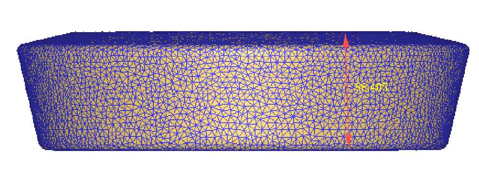
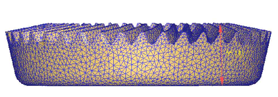
As shown in (a) and (b) in the figure, the grid diagrams before and after the forming of the driven spiral bevel gear are shown respectively. It can be seen from figure (b) that the blank in contact with the tooth top of the spiral bevel gear die is compressed along the longitudinal line, elongated laterally, and the mesh density is high. Finally, the tooth shape part of the driven spiral bevel gear is formed. The mesh along the tooth surface part is more dense than the mesh inside the tooth shape. This is because the metal on the surface part is in direct contact with the tooth die. In the forming process, the mesh is easy to be distorted, so the mesh is re divided. In the middle part of the spiral bevel gear, the mesh is obviously larger, because in the whole simulation process, the metal in this part is in uniform deformation, and the deformation is very small, so there is no mesh distortion. Figure (a) shows the blank grid before deformation, with a height of about 58.1mm, and figure (b) shows the blank grid after deformation, with a height of about 55.4mm. This figure clearly shows the shape changes of the grid before and after deformation. It can be seen that the blank height decreases.