
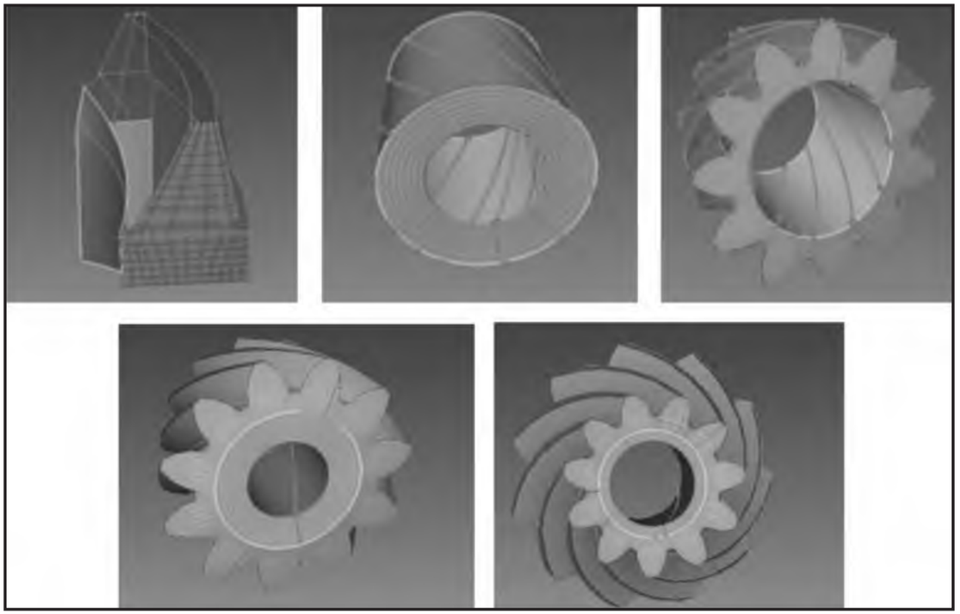
1. Grid division
Spiral bevel gear has spatial geometric complexity, which makes the volume mesh of spiral bevel gear directly generated by ABAQUS and other finite element software have a large degree of bending deformation, reduces the mesh quality, and will greatly hinder the finite element analysis. So we use the finite element pre-processing software Hypermesh to mesh the spiral bevel gear. The division method is shown in Figure 1. First, the shell element mesh as shown in the figure is generated on the surface of a tooth, and then the mesh and feature line are selected on the drag operation panel of the hexahedral mesh division solid interface, and finally the cutting of the whole solid is completed.
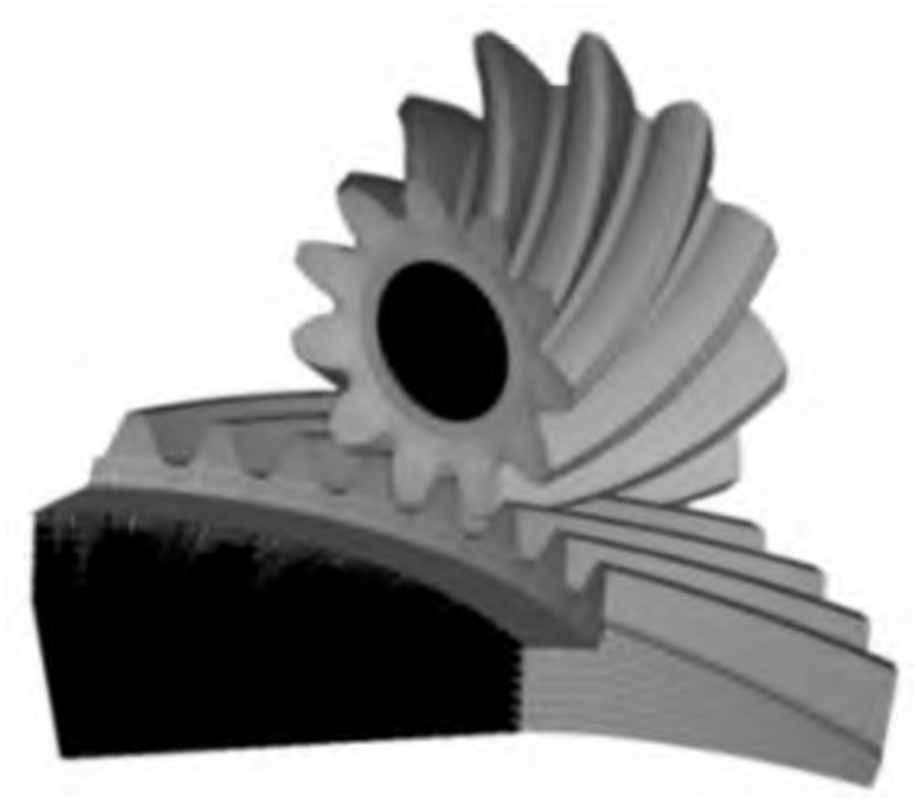
2. Pretreatment of finite element
The established finite element mesh model is followed by the finite element pretreatment of the spiral bevel gear, as shown in Figure 2.
(1) Set material properties, as shown in Table.
| Material name | Modulus of elasticity (GPa) | Poisson’s ratio | Yield strength (MPa) |
| 20CrMnTi | 212 | 0.289 | 835 |
(2) Establish interaction and constraints: select the large gear surface and the small gear surface as the interaction surface. Set the normal contact attribute as hard contact, and set the friction coefficient of the tangent contact attribute as 0.1. Next, create a reference point on the axis of the pinion and pinion, and create a “coupling” constraint between the reference point and the spiral bevel gear.
(3) Set up the analysis step: because the dynamic and static analysis of the model are done here, the dynamic and static analysis steps are created by using the dynamic and static modules of ABAQUS software.
(4) Boundary conditions and load settings under static state: ① Fix all constraints of the big gear and apply small rotation to the small gear to eliminate the gear tooth clearance. ② The small amount of rotation is still applied to the pinion, and the axial constraint of the big gear is released to establish the initial condition of the spiral bevel gear transmission contact. ③ Apply a large amount of rotation to the pinion, so that the pinion is enough to drive the big gear to engage the spiral bevel gear normally. Considering the finite element analysis results under three working conditions, the large gear is loaded with 300N · m, 500N · m and 800N · m.
(5) Boundary conditions and load settings under dynamic conditions: fix other degrees of freedom, release the rotational degrees of freedom along the axis at the reference point of the big wheel and the small wheel, and define the rotation speed of the small wheel as 20rad/s, the load on the big wheel is 500N · m, and the time t=0.02s.
(6) The output results are: the contact stress of big and small gears, the maximum stress of big and small gear tooth root, and the angle of big and small gears.