
ANSYS software itself has powerful meshing function, so ANSYS software is used for meshing. Import the 3D model built in SolidWorks software into ANSYS, as shown in Figure 1.
In mesh generation, it is very important to grasp the size of the mesh, which directly affects the In mesh generation, it is very important to grasp the size of the mesh, which directly affects the convergence of the numerical calculation process and the length of the calculation time. For the mesh size, the smaller is not the better. From the perspective of numerical calculation, the smaller the mesh size, the more the number of meshes, the higher the calculation accuracy and the more accurate the solution result. However, if the number of grids is too large, the cumulative calculation error in the calculation process will be too large, resulting in non convergence. Therefore, the grid size should be reasonably controlled. From the perspective of time cost, we should fully consider the computing power of existing computer hardware. When meshing the three-dimensional model, we should also consider the research purpose, refine the mesh of the key research objects in the model, and roughen the mesh of the less important parts. This paper mainly analyzes the temperature field change and distribution of bevel gear in the process of dual frequency induction heating, so the heat affected zone of bevel gear is the key research object of this paper.
After completing the numerical simulation of the dual frequency induction heating process of the bevel gear, it is necessary to analyze the distribution of the temperature field, magnetic induction intensity and current density of the hardened layer of the bevel gear. In order to improve the simulation accuracy and facilitate the extraction of data, it is necessary to refine the surface grid of the bevel gear.
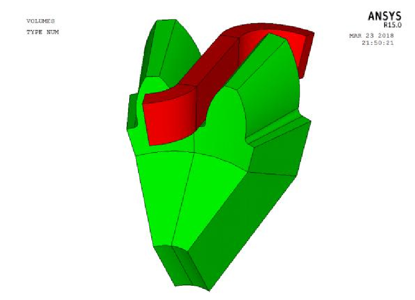


Figure 1 is the bevel gear and coil model imported from Solidworks software into ANSYS software, and Figure 2 is the bevel gear mesh model. As can be seen from Figure 2, the mesh density of the tooth and root of the bevel gear is dense and regular, which is divided and generated by sweeping, while the tooth base is less affected by the magnetic field and almost does not participate in the induction heating calculation, so the divided mesh is relatively coarse, which can save a lot of calculation time. In order to avoid the phenomenon of non convergence in numerical calculation, we should avoid the sudden change of adjacent grid size and produce abnormal grid. Therefore, the grid size from the tooth profile surface of bevel gear model to the gear matrix should be gradually increased. Fig. 3 is an overall view of the mesh model of the induction coil and bevel gear.