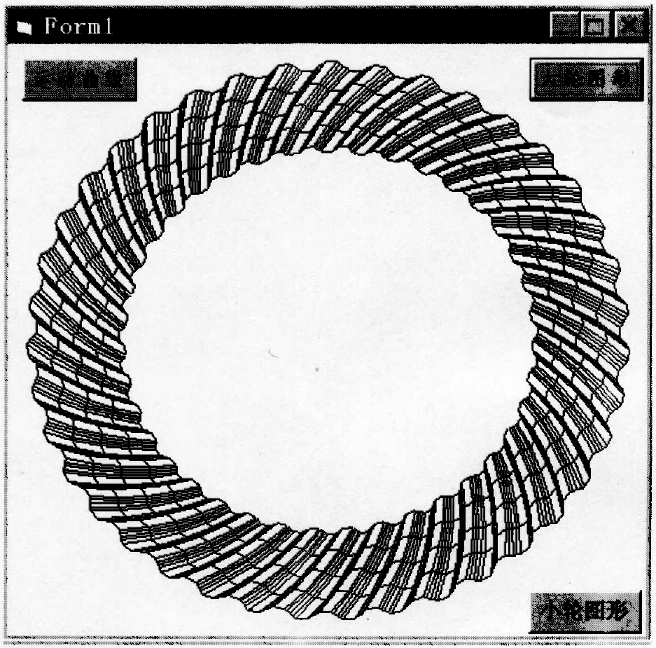
According to the establishment of coordinate system and spatial matrix transformation, such as the distance from any point of wheel blank to Z’1 τ R and RZ of the point in the {o’1, X’1, y’1, Z’1} coordinate system, Q can be obtained, θ, t. Then substitute (Rx, ry, RZ) t to find the fixed position (Rx, ry, RZ) t of this point on the wheel blank. In this way, the tooth surface equation can be obtained by using RR and RZ variables. The program block diagram of drawing large and small wheel graphics and large and small wheel graphics are as follows:
Spiral bevel gear is a point contact conjugate surface, and the tooth surface curve is not a complete involute. Therefore, under no-load condition, the instantaneous transmission ratio is not constant, which is consistent with the theoretical value only at one point, and different from the theoretical roll ratio at other points.
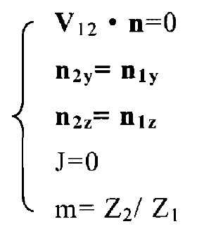
After the gear is machined, the quality of the tooth surface contact area shall be checked, and the size and shape of the tooth surface contact area shall be observed at the specified position. The mathematical model of this process is to specify a point m on the big wheel and calculate Q by mathematical iteration, θ, t。 Then change the installation position of the big and small wheels so that the big tooth surface and the small wheel tooth surface are in contact at a given point. We require that the meshing track of the gear pair passes through this point without changing the installation value of the large wheel (i.e. J = 0), and the transmission ratio at this point is equal to the theoretical value Z2 / Z1. Q on the wheel, θ, T and the angle turned to make the big wheel points mesh correctly η 1, η 2 is the variable, and the corresponding points on the small wheel can be obtained by using the following equations, and the values of V, h and J can be obtained.

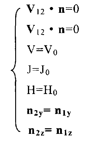
During gear transmission, the pinion is active and the big gear is passive. The rotation of the pinion is generally constant. Because the tooth surface shape is not a complete involute and the transmission ratio is not constant, there is a difference △ between the actual rotation angle and the theoretical rotation angle of the big wheel ε, Given a constant speed angle increment △ η, Find the corresponding contact point Q of the big wheel, θ, t. And large wheel angle η‘。 Establish the following equations to T1, θ 1,q1,t2, θ 2,q2, η‘ Is a variable:

H – change amount of small wheel installation distance, which is positive when adjusted to the big end, and negative when adjusted to the contrary;
V – offset distance of small wheel, the change in the vertical direction of small wheel, upward is positive and downward is negative;
J – change amount of large wheel mounting distance, which is positive when adjusted to the large end, and negative when adjusted to the large end.
From the above equations, each variable, large wheel angle increment △ η=η’-η, The theoretical angle of the large wheel is △ η X Z2 / Z1, so △ ε=(η’-η)- △ η X Z2 / Z1, this value is very small, and it is enlarged 100000 times when making the motion curve.


