Abstract
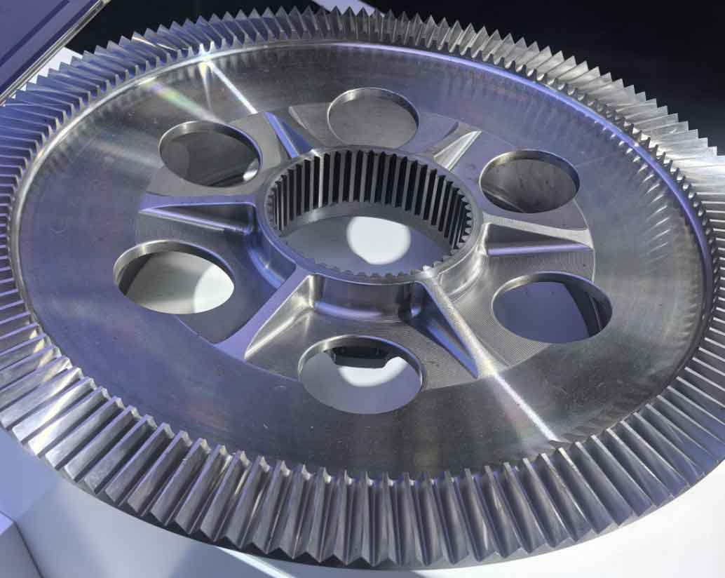
Herringbone gear, characterized by their symmetrical arrangement of left- and right-handed helical gears, are widely used in high-speed trains, marine propulsion, and aerospace systems due to their high load capacity, smooth transmission, and axial force cancellation. However, manufacturing and assembly errors often introduce asymmetrical deviations between the left and right tooth surfaces, leading to non-uniform load distribution and dynamic instability. This study proposes a novel axial displacement iteration method based on Newton’s algorithm to address the limitations of traditional iterative approaches in handling large-scale errors. A loaded tooth contact analysis (LTCA) model is developed by integrating finite element method (FEM) and finite line contact theory. The model accounts for variations in helix angles at different meshing points and evaluates the effects of lead crowning modification and tooth surface stagger angle on meshing stiffness, transmission error, and load distribution. Key findings reveal that lead crowning modification reduces time-varying meshing stiffness by 38% and increases average meshing error by 39% when the modification amplitude grows from 2 μm to 15 μm. Meanwhile, increasing the stagger angle phase difference from 0 to π decreases the amplitude of time-varying meshing stiffness and meshing error by 54% and 79%, respectively. These results provide critical insights into optimizing herringbone gear design for enhanced stability and reduced vibration.

Introduction
Herringbone gear is pivotal in power transmission systems requiring high torque and minimal axial thrust. Their unique double-helical structure eliminates axial forces, making them ideal for high-speed applications. However, manufacturing imperfections, such as asymmetrical tooth deviations and alignment errors, disrupt load balance and amplify dynamic excitations. Traditional LTCA models struggle with convergence under large errors, necessitating advanced computational methods.
This work introduces a Newton iteration-based LTCA model to resolve axial displacement in herringbone gear with lead crowning modification and stagger angles. By incorporating helix angle variations and nonlinear contact mechanics, the model quantifies how geometric modifications influence meshing behavior. The analysis bridges gaps in existing literature by addressing the interplay between lead crowning, stagger angle, and axial force equilibrium.
Methodology
1. Load-Deformation Coordination Equations
The meshing process of herringbone gear is modeled as elastic contact between two cylindrical bodies. The deformation coordination equation at each contact point is expressed as:upj+ugj+ϵj=δupj+ugj+ϵj=δ
where upjupj and ugjugj are the elastic deformations of the driving and driven gears at point jj, ϵjϵj is the initial gap, and δδ is the relative contact displacement.
For finite line contact, the local deformation uejuej at point jj is derived from Hertzian theory:uej=fnjnE∗ln(6.59ljE∗(Rpj+Rgj))uej=nE∗fnjln(6.59ljE∗(Rpj+Rgj))E∗=(1−νp2Ep+1−νg2Eg)−1E∗=(Ep1−νp2+Eg1−νg2)−1
Here, fnjfnj is the normal force, ljlj is contact length, RpjRpj and RgjRgj are curvature radii, and E∗E∗ is the effective modulus.
2. Axial Force Balance and Newton Iteration
The axial force equilibrium equation for herringbone gear is:∑i=1kLfnicosαicosγi=∑j=1kRfnjcosαjcosγji=1∑kLfnicosαicosγi=j=1∑kRfnjcosαjcosγj
where kLkL and kRkR are the numbers of meshing points on the left and right helical pairs, and γiγi is the axial inclination angle.
Newton’s iteration method solves the nonlinear equation ΔFa(η)=0ΔFa(η)=0, where ηη is axial displacement. The iteration formula is:ηn+1=ηn−ΔFa(ηn)Knηn+1=ηn−KnΔFa(ηn)
with the secant slope Kn=ΔFa(ηn)−ΔFa(ηn−1)ηn−ηn−1Kn=ηn−ηn−1ΔFa(ηn)−ΔFa(ηn−1).
3. Lead Crowning Modification
Lead crowning modifies the tooth profile to a circular arc, reducing edge loading. The crowning depth CiCi at position LiLi is:Ci=r−r2−(Licosβb)2Ci=r−r2−(cosβbLi)2
where rr is the arc radius and βbβb is the base circle helix angle.
4. Stagger Angle Definition
The stagger angle ΓsΓs represents the angular offset between left and right helical pairs. For a gear with NN teeth, ΓsΓs ranges from 0 to π/Nπ/N, corresponding to 0–50% stagger proportion (Table 1).
Table 1. Relationship between stagger angle, phase difference, and stagger proportion
| Stagger Angle (ΓsΓs) | Phase Difference (γsγs) | Stagger Proportion (%) |
|---|---|---|
| π/4Nπ/4N | π/4π/4 | 12.5 |
| π/2Nπ/2N | π/2π/2 | 25.0 |
| 3π/4N3π/4N | 3π/43π/4 | 37.5 |
| π/Nπ/N | ππ | 50.0 |
Results and Discussion
1. Impact of Lead Crowning Modification
Under a 500 N·m torque, increasing lead crowning from 2 μm to 15 μm alters meshing behavior:
- Time-varying meshing stiffness (kmkm): Mean stiffness decreases by 38%, while amplitude fluctuates nonlinearly (Table 2).
- Composite meshing error (emem): Mean error increases by 39%, with pronounced peaks in double-tooth engagement zones.
Table 2. Mean values and amplitudes of meshing stiffness and error under varying crowning
| CmaxCmax (μm) | kmkm (kN/mm) | emem (μm) | ||
|---|---|---|---|---|
| Mean | Amplitude | Mean | Amplitude | |
| 2 | 1622.15 | 282.67 | 1.61 | 1.94 |
| 15 | 1004.10 | 426.93 | 2.25 | 2.55 |
Load distribution shifts toward the tooth center as crowning increases. At Cmax=15μmCmax=15μm, the maximum normal force at the tooth center rises from 100 N to 370 N.
2. Influence of Stagger Angle
A phase difference γsγs from 0 to ππ yields:
- Axial displacement: Oscillatory motion balances axial forces, reducing residual imbalance to <0.02 N.
- Meshing stiffness and error: Stagger angles enhance stiffness uniformity and suppress error fluctuations (Figure 1).
Key Metrics
- kmkm: Mean increases by 2.5%, amplitude drops by 54%.
- emem: Mean decreases by 16%, amplitude drops by 79%.
3. Load Distribution Under Stagger Angle
Stagger angles redistribute loads across meshing cycles. At 50% stagger, the right helical pair’s load transitions lag the left by half a cycle, mitigating peak forces (Figure 2).
Conclusion
This study advances the understanding of herringbone gear dynamics by integrating lead crowning modification and stagger angle effects into a Newton-based LTCA model. Key outcomes include:
- Lead crowning reduces edge loading but increases meshing error, necessitating trade-offs in design.
- Stagger angles phase-shift meshing events, dampening stiffness and error fluctuations by up to 79%.
- Newton’s iteration outperforms traditional methods, reducing computation time by 70% under small errors.
These findings enable optimized herringbone gear configurations for high-speed applications, balancing load distribution, noise reduction, and operational stability.
